2003 Toyota Tacoma Parts Diagram: 2026 Component Breakdown

The 2003 Toyota Tacoma parts diagram maps the mechanical and electrical system layout across 2.4L (2RZ-FE), 2.7L (3RZ-FE), and 3.4L (5VZ-FE) configurations. It details sub-assemblies including front double-wishbone suspension components, frame crossmembers, steering racks, and fuel injection routing, referencing OEM part groups like 48068-35081 lower control arms and vacuum line pathways.
📌 Key Takeaways
- Specific engine diagrams differentiate 2RZ-FE/3RZ-FE 4-cylinder layouts from the 5VZ-FE 3.4L V6 engine configuration.
- Critical identification requires verifying your VIN 4th and 5th digits to confirm standard cab, Xtracab, or Double Cab frame structure.
- Lower ball joint bolts require strictly 59 lb-ft (80 Nm) torque with red threadlocker to avoid catastrophic front suspension failure.
- The primary structural failure point on 2003 models is frame rust perforation, particularly along the boxed rails near the catalytic converter.
- Routine bolt-on component replacements are suitable for DIYers, but structural frame welding and differential rebuilds necessitate professional service.
Navigating a 2003 Toyota Tacoma parts diagram requires a clear understanding of the late first-generation (1995.5–2004) N140/N150/N160/N170 platform. By the 2003 model year, Toyota implemented major electronic and mechanical updates, including drive-by-wire Electronic Throttle Control Systems (ETCS-i) on V6 engines, standardized Vehicle Stability Control (VSC) options, and revised front suspension architectures. Whether you are rebuilding a front steering knuckle, rebuilding an A340F automatic transmission, or isolating a chassis ground, exploded OEM schematics eliminate guesswork by mapping individual components to their exact production assemblies.
This technical guide deconstructs the 2003 Toyota Tacoma parts catalog. It covers structural and mechanical variations across cab, drivetrain, and chassis subassemblies, enabling you to extract correct Part Name Codes (PNC) and locate the precise 10-digit OEM part numbers required for exact-fit maintenance and restoration.


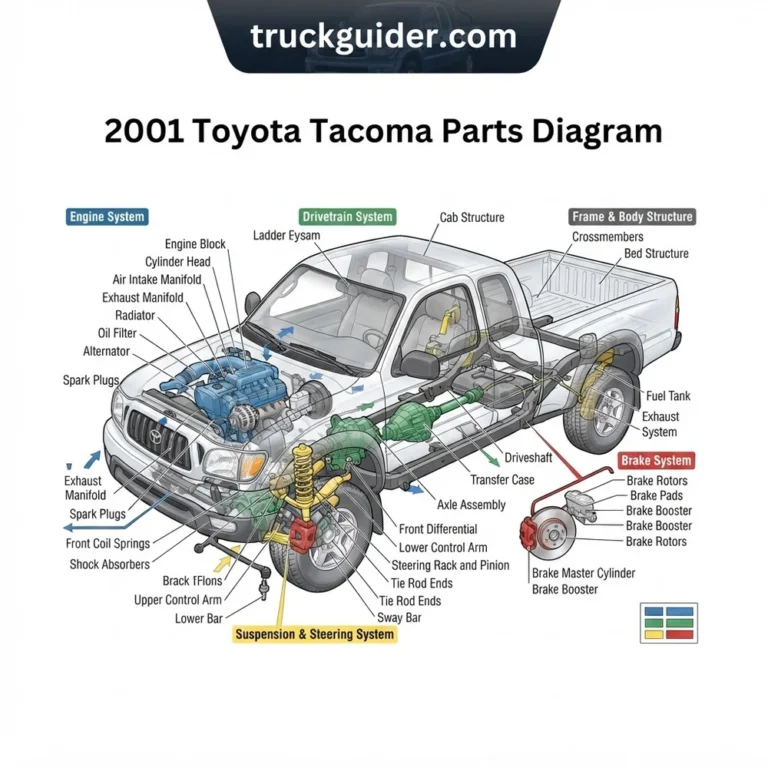
Exploded mechanical schematic detailing the front suspension, chassis crossmembers, powertrain positioning, and drivetrain architecture of the first-generation platform.
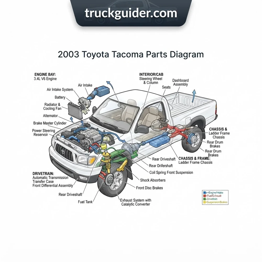
2003 Toyota Tacoma Schematic: Key Drivetrain and Cab Configurations


Before pulling part numbers from an OEM schematic, you must identify your vehicle’s specific platform architecture. The 2003 model year encompasses three distinct cab configurations, three engine options, and two primary suspension/chassis platforms that do not share critical front-end or chassis components.
The most critical structural division in the 2003 parts catalog lies between the 5-lug standard two-wheel-drive (2WD) chassis and the 6-lug platform. The 6-lug platform comprises both the traditional Four-Wheel Drive (4WD) and the 2WD PreRunner. Although the PreRunner lacks a front transfer case and differential, it uses the 4WD chassis frame, high-mount upper control arms, 6×139.7mm (6×5.5 inch) wheel hubs, and rear leaf-over-axle configuration. Consequently, sourcing front suspension or brake parts using a generic “2WD Tacoma” schematic frequently results in receiving 5-lug components that physically cannot mount to a PreRunner chassis.
| Chassis Platform | Engine & Trans Codes | Lug Pattern & Track | Frame Type & Code | Suspension Geometry |
|---|---|---|---|---|
| Base 2WD (Regular & Xtracab) | 2.4L 2RZ-FE W59 Manual / A43D Auto |
5×114.3mm (5×4.5 in) Track: 57.1 in |
Low-slung C-channel/box RZN140 / RZN150 |
Coil-spring over LCA; spring in compression; low-mount ball joint |
| PreRunner 2WD (All Cabs) | 2.7L 3RZ-FE / 3.4L 5VZ-FE A340E Automatic |
6×139.7mm (6×5.5 in) Track: 60.6 in |
Raised 4WD boxed/channel RZN161 / VZN170 |
High-mount UCA; coilover strut; lower ball joint in tension |
| 4WD Manual/Auto (All Cabs) | 2.7L 3RZ-FE / 3.4L 5VZ-FE W59 / R150F / A340F |
6×139.7mm (6×5.5 in) Track: 60.6 in |
Raised 4WD boxed/channel RZN196 / VZN195 |
Coilover strut; live front differential (ADD); high-mount UCA |
Cab configuration introduces further schematic divergence regarding wheelbases, driveshafts, and body mount bushings. The 2003 Regular Cab utilizes a 103.3-inch wheelbase with a single-piece or short-coupled driveshaft. The Xtracab features a 121.9-inch wheelbase, requiring a two-piece driveshaft equipped with a center support carrier bearing (PNC 37230). The Double Cab, introduced late in the first generation, shares the 121.9-inch wheelbase of the Xtracab but uses a shortened 61.5-inch bed, requiring unique cab mounting cushions, rear brake hydraulic hardlines, and door weatherstripping configurations. Consult our first-gen Tacoma frame rust inspection protocol if you are verifying frame code stamping locations along the passenger side boxed rail.
2003 Toyota Tacoma Parts Diagram: Component Breakdown by System


Front Suspension and Steering Diagram


The 6-lug (4WD/PreRunner) front suspension assembly uses an independent double-wishbone architecture. The upper control arm (UCA, PNC 48066 RH / 48067 LH) mounts directly above the steering knuckle, attaching to the frame through dual eccentric alignment cams (PNC 48409) that regulate camber and caster. The lower control arm (LCA, PNC 48068 RH / 48069 LH) provides the mounting seat for the lower strut eyelet and the anti-sway bar end link.


Front Lower Ball Joint (LBJ) to Steering Knuckle Flange Bolts: OEM Part Number 90119-10933. Thread pitch: M10x1.25. Torque specification: 59 ft-lb (80 Nm). Always apply medium-strength (blue) threadlocker compound to the internal threads prior to installation.
The steering linkage schematic details a power rack-and-pinion assembly (PNC 44250) secured to the front crossmember via two D-shaped polyurethane or rubber bushings and a vertical through-bolt sleeve. The outer tie rod ends (PNC 45046 RH / 45047 LH) thread onto the inner rack joints (PNC 45503) and mate to the lower ball joint housing, rather than directly to the knuckle spindle. This structural configuration places the lower ball joint (LBJ, PNC 43330 RH / 43340 LH) in tension; vehicle weight constantly acts to pull the ball stud out of its housing rather than pushing it in, making precise OEM component selection essential.
Engine Assembly and ETCS-i Induction Diagram
The 2003 model year marked a significant revision in the 3.4L V6 (5VZ-FE) and 2.7L I4 (3RZ-FE) air intake schematics. The 5VZ-FE engine diagram eliminates the traditional idle air control valve (IACV) and mechanical throttle cable linkage used from 1995 to 2002. Instead, it incorporates an Electronic Throttle Control System (ETCS-i), which integrates:
- Drive-by-wire throttle body assembly (PNC 22030-62020) containing the integrated throttle control motor and throttle position sensor (TPS).
- Accelerator pedal position sensor (APPS) mounted directly to the bellcrank assembly on the intake manifold runner.
- Coil-on-plug ignition layout eliminating the earlier waste-spark system; 2003 V6 engines utilize three dual-post ignition coils (PNC 90919-02212) feeding three direct cylinders and three secondary plug wires (PNC 19037-62010) jumping to the opposite bank.
For servicing the front accessory drive and cam timing belts, refer to our comprehensive 5VZ-FE timing belt replacement procedure for torque values on the dynamic hydraulic tensioner (PNC 13540-62021) and idler pulleys.



Chassis and Frame Diagram
The 2003 Tacoma chassis blueprint consists of a hybrid boxed and open C-channel architecture manufactured for Toyota by Dana Corporation. The forward section, extending from the front bumper mounts through the transmission crossmember (Crossmember No. 3), utilizes fully boxed, welded rectangular tubing. Directly under the cab-to-bed transition point, the structure transitions into an open C-channel side rail design.
Key callout references in this section include:
- Crossmember No. 1 (PNC 51201): Supports the lower radiator mounts and front dynamic recovery hook.
- Crossmember No. 2 (PNC 51202): Bridges the lower control arm forward pivots and integrates front differential mounting drop-brackets on 4WD applications.
- Rear Leaf Spring Hangers (PNC 51701 front / 51703 rear shackle): Riveted directly to the exterior of the C-channel frame rails.
Exhaust and Emissions Layout Diagram


Due to tightening CARB standards, all 2003 Tacomas feature a dual-catalytic converter system regardless of whether they were designated for California or Federal delivery. The front exhaust pipe (PNC 17410) integrates an upstream planar Air-Fuel Ratio (A/F) Sensor (Bank 1, Sensor 1; PNC 89467-35011 on 5VZ-FE) positioned before the primary catalytic converter.
Do not interchange upstream Bank 1 Sensor 1 with downstream Bank 1 Sensor 2. The upstream sensor is a wideband Air-Fuel ratio sensor operating on variable current (mA), while the downstream sensor (PNC 89465) is a conventional zirconia oxygen sensor outputting a 0.1 to 0.9V signal. Mixing these components triggers diagnostic trouble codes P0125 and P0171.
The EVAP canister assembly (PNC 77740) on the 2003 model is situated under the bed adjacent to the fuel tank, replacing the earlier engine-bay-mounted design. This assembly includes integrated Vapor Pressure Sensors and canister closed valves (CCV) managed through dedicated engine harness wiring.
How to Read a 2003 Toyota Tacoma Parts Diagram Step by Step


Decoding a Toyota Electronic Parts Catalog (EPC) schematic requires understanding how system callouts convert to orderable 10-digit part numbers. Follow this standardized procedure to avoid sourcing incorrect year-split or trim-split components.


-
Decode the Complete VIN and Frame Code:
Locate the 17-digit Vehicle Identification Number (VIN) on the driver side door jamb certification label. Below the barcode, identify the model designation string (e.g.,VZN170L-CRMDKAB).VZN170identifies a 3.4L V6 PreRunner Extra/Double Cab.VZN195identifies a 3.4L V6 4WD Double Cab.RZN140identifies a 2.4L 4-cylinder 5-lug chassis.
Matching this code prevents pulling parts from an incompatible suspension or drivetrain schematic.
-
Verify the Vehicle Production Date Split:
Components inside the 2003 model year parts diagrams are segmented by production date (MM/YY), not just model year. The 2003 run spanned from September 2002 through August 2003. Look at the upper right corner of the door jamb plate for the build date. For example, antilock braking system (ABS) wire harnesses and steering column intermediate shafts feature a direct mid-cycle production revision starting with 01/2003 builds. -
Locate the Part Name Code (PNC) on the Exploded Schematic:
OEM exploded diagrams do not display raw 10-digit part numbers on the illustration sheet. Instead, they point to components using 5-digit or 6-digit basic callouts known as Part Name Codes (PNC).- Illustration callout
48131represents the front coil spring. - Illustration callout
43330represents the right-hand lower ball joint assembly. - Illustration callout
04479represents a brake caliper rebuild seal kit.
- Illustration callout
-
Cross-Reference the PNC to the Specific Part Number Matrix:
Once the PNC is selected, cross-reference that callout against the parts list table on the adjoining catalog page. Filter the list using your VIN-derived Frame Code and Production Date. The catalog expands the 5-digit PNC into a 10-digit or 12-digit ordering number formatted asXXXXX-XXXXX(e.g.,43330-39585for the revised 4WD/PreRunner LBJ). The first 5 digits represent the component family; the final 5 digits represent vehicle design revisions, coatings, and platform variations.
If a part number features a trailing two-digit code (such as -01 or -C0), it designates factory interior trim color matching (e.g., Oak vs. Moon Mist/Gray) or exterior paint coding on body components like side-view mirror shells.
Troubleshooting Common 2003 Tacoma Parts Diagram and Fitment Errors



When referencing technical schematics for the 2003 Tacoma, mechanics frequently encounter component mismatches caused by subtle mid-generation facelifts, recall updates, and overlapping trim names.
1. Lower Ball Joint (LBJ) Hardware and Casting Variations
The most catastrophic fitment errors occur within the front lower ball joint assembly. Because the ball stud is loaded in tension, premature failure occurred on early designs, prompting Toyota Safety Recall 05V225000.
The updated diagram replaces the original ball joint castings with reinforced housings. Furthermore, the four mounting bolts securing the LBJ to the knuckle were updated from standard flanged-head bolts to high-strength flanged bolts requiring blue threadlocker. Technicians referencing obsolete aftermarket diagrams often mistake the 5-lug ball joint (PNC 43330-39415, small bolt circle, compression-loaded) for the PreRunner/4WD ball joint (PNC 43330-39585, elongated flange ears, tension-loaded). Sourcing this component by vehicle model name alone, rather than cross-referencing the 6-lug spindle geometry, can lead to incorrect part selection.
| Assembly Component | 5-Lug Base Chassis | 6-Lug PreRunner / 4WD | Critical Fitment Distinction |
|---|---|---|---|
| Lower Ball Joint (RH) | 43330-39415 | 43330-39585 | Completely different bolt patterns; 6-lug mounts tie rod directly to LBJ body. |
| Front Brake Rotor | 43512-35200 (255mm) | 43512-04020 (297mm) | Diameter and hat depth differ; 5-lug rotor will not slide over 6-lug hub flange. |
| Steering Rack Assembly | 44250-35030 | 44250-35042 | Stroke length, inner tie rod thread reach, and rack housing diameter differ. |
2. Frame Structural Reinforcement and Crossmember Fitment
The NHTSA frame rust campaigns led to thousands of 2003 Tacoma frames being replaced with revised service frames or retrofitted with structural plate kits. When consulting chassis blueprints for frame rail repairs:
- Service Frame Differences: Replacement service frames distributed post-2008 by Toyota feature fully coated inner boxed rails and updated leaf spring shackle hanger brackets (PNC 51040-35430) with reinforced weld fillets.
- Crossmember No. 4 (Spare Tire Carrier): If your truck was retrofitted under campaign CSN-90D, the rear crossmember and spare tire hoist assembly may match the 2004–2005 transitional blueprint rather than the baseline 2003 factory layout. Measure the hoist bracket bolt-spacing (2.75 inches versus 3.5 inches) before ordering a replacement crank hoist (PNC 51900-35280).
3. Driveshaft Center Support Bearing Orientation
On Xtracab and Double Cab models, the two-piece driveshaft schematic shows a center support bearing (carrier bearing, PNC 37230-35130). A frequent assembly error stems from misinterpreting the directional arrow on the rubber carrier bracket shown in the exploded view. Installing this bearing backward tilts the front slip yoke off-axis, introducing a severe 15–25 mph driveline shudder under acceleration.
The molded rubber flange on the carrier bearing must offset toward the front of the vehicle. For complete driveline service steps, consult our technical breakdown of the Toyota A340E transmission rebuild guide to verify output shaft splines and transfer case companion flange mating steps.
Frequently Asked Questions: 2003 Toyota Tacoma Parts Blueprint Analysis
Where is the exact engine serial number stamped according to the 5VZ-FE schematic?


On the 3.4L 5VZ-FE V6 engine block, the serial number is stamped on a machined flat boss located on the left (driver) side rear of the cylinder block, just below the cylinder head mating surface and behind the oil filter bracket assembly. On 4-cylinder engines (2RZ-FE and 3RZ-FE), the identification number is stamped on the right (passenger) side forward section of the block, near the engine mount casting bracket.
Can I use front brake caliper parts from a 4WD Tacoma diagram on a PreRunner?
Yes. The 2003 Tacoma PreRunner shares identical front braking hardware with the 4WD model of the same cab configuration. Both vehicles utilize dual-piston or four-piston cast-iron calipers (Casting code S12WE for 15-inch stock wheels or S13WE for 16-inch stock wheels, PNC 47730-35080 RH / 47750-35080 LH). They do not share front brake calipers with the 5-lug base 2WD model, which uses a smaller single-piston sliding caliper (PNC 47730-35110).
Why does my 2003 Tacoma throttle body parts diagram not show an Idle Air Control (IAC) valve?
For the 2003 model year, the 5VZ-FE engine was updated to the ETCS-i system (Electronic Throttle Control System with intelligence). This design eliminated the idle air control valve, the auxiliary cold start air pipe, and the mechanical idle bypass screw used on 1995–2002 models. Idle air volume is managed entirely by the ECU commanding the internal electronic throttle plate actuator motor (PNC 22030-62020) to adjust opening angles.
How do I differentiate between Federal and California emissions components on the 2003 exhaust schematic?
By the 2003 model year, Toyota largely consolidated emissions architectures across all 50 states for light trucks. To verify your specific emissions package, check the under-hood Vehicle Emission Control Information (VECI) label located on the underside of the hood. If the label states “Conforms to California Regulations” or displays engine family group 3TYXT03.4FAR, order the A/F ratio sensor (PNC 89467-35011) and dual underfloor catalytic converters shown in the California-specific sub-schematic. Federal-only designated systems (rare for 2003) use standard heated oxygen sensors (PNC 89465-35580) in the upstream location with alternative flange spacing.
Step-by-Step Guide to Understanding the 2003 Toyota Tacoma Parts Diagram
Identify – Determine your vehicle’s exact engine code (2RZ, 3RZ, or 5VZ) and drive type (2WD, PreRunner, or 4WD) from the door jamb VIN tag.
Locate – Find the specific subsystem section in the master diagram catalog, matching major component groups such as frame, engine, or suspension.
Reference – Match the illustration callout number to the corresponding OEM part index to confirm exact fastener sizes, bracket orientations, and mating gaskets.
Connect/Route – Assemble or route each component following the diagram’s directional arrows, maintaining factory cable, hose, and wiring harness clips.
Verify – Torque all fasteners to the specified ratings provided in the service manual, checking alignment marks on rotated hardware like control arm cam bolts.
Troubleshoot – Check adjacent assembly groups in the diagram if components bind, leak, or misalign, confirming washer stacking order and correct bracket seating.