2005 GMC Sierra Fuse Box Diagram: 2026 Repair Guide

The 2005 GMC Sierra features two main fuse blocks: the underhood junction block mounted beside the driver-side master cylinder, and the interior instrument panel fuse block behind the driver-side dashboard end-cap. The OBD-II port and diagnostic tools draw 12-volt battery power directly through the 15-amp CIG LTR fuse in the underhood block.
📌 Key Takeaways
- The 15A CIG LTR fuse in the underhood panel powers both the auxiliary power outlets and the unswitched pin 16 on the OBD-II diagnostic port.
- Underhood electrical center cover provides an internal component map; securing the M6 center mounting bolt requires an 89 lb-in (10 Nm) torque spec.
- A blown 20A ECM B fuse directly cuts 12V battery feed to the ECU, triggering crank-no-start conditions without logging an active diagnostic code.
- Internal trace fretting or corrosion beneath the underhood junction block is a primary cause of erratic intermittent circuit open conditions.
- Replace standard mini-blade fuses independently, but consult an automotive technician if circuit testing shows melted terminal blocks or continuous overdraw.
Diagnostic electrical work on the 2005 GMC Sierra 1500, 2500HD, and 3500 series demands a precise understanding of the General Motors GMT800 power distribution network. Whether you are chasing an elusive parasitic draw, addressing an uncommanded fuel pump shutdown, or resolving sensor reference faults causing intermittent drivability issues, mastering the fuse center layout is critical. This guide provides detailed terminal pinout mappings, circuit-by-circuit amperage ratings, practical multimeter diagnostics, and platform-specific electrical architecture notes to help you trace faults accurately and protect sensitive onboard microcontrollers from damage.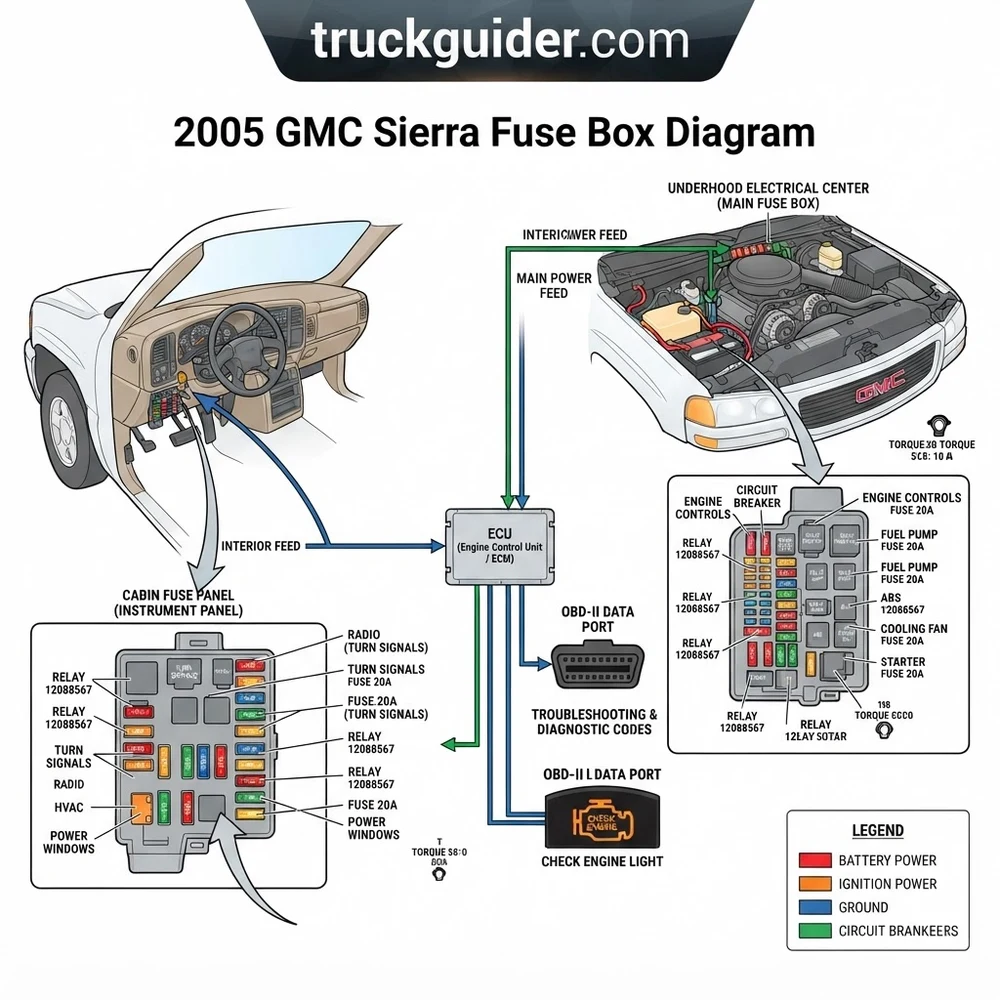
2005 GMC Sierra Fuse Box Locations Across the GMT800 Platform


General Motors engineered the 2005 GMT800 platform with three centralized electrical distribution hubs. Isolating circuit malfunctions requires knowing the exact physical access methods and module boundaries for each junction center.


Underhood Electrical Center (Engine Bay Fuse Block)


The primary power distribution center resides in the engine bay on the driver-side inner fender apron, positioned directly between the master cylinder assembly and the remote positive battery terminal post. This electrical block handles high-current downstream loads, including ignition circuits, electric cooling fans, lighting infrastructure, and powertrain sub-harnesses. To open the assembly, release the two retaining thumb-tabs along the perimeter of the black thermo-plastic dust cover and lift it straight upward. On the underside of this lid, you will find an embossed component schematic showing the factory relay and fuse spatial arrangement. The underhood center also anchors the primary 12-volt battery distribution bus bar through heavy-gauge eyelet studs.
Instrument Panel (I/P) Fuse Block
The interior Instrument Panel fuse block is located on the extreme driver-side outboard edge of the dashboard structure. Access to this panel is only possible with the front driver-side door swung fully open. Locate the textured plastic trim access panel on the structural end-cap of the dash, insert a non-marring pry tool into the upper release slot, and pivot the cover outward toward the door jamb to disengage the metal tension clips. This panel safeguards vehicle interior accessories, cabin environmental controls, supplemental restraint systems (airbags), instrumentation clusters, and key serial data link circuits.
Center Instrument Panel Utility Block
Positioned under the driver-side dashboard bulkhead, immediately to the left of the steering column and brake pedal bracket assembly, lies the Center Instrument Panel Utility Block. This junction center utilizes multi-pin harness connectors rather than consumer-accessible blade fuses. It houses primary junction taps for aftermarket equipment interfaces, body-harness cross-connections, trailering brake controller pigtails, and specialty equipment option (SEO) modules. Gaining access requires removing the lower dash knee bolster panel using a 7mm hex socket and pulling down the acoustic insulator panel.
For comprehensive electrical schematics covering body integration systems, refer to our companion guides on GMT800 body control module harness layouts and factory auxiliary ground path points.
2005 GMC Sierra Fuse Box Diagram: Circuit Identification and Specs


The electrical system utilizes standard color-coded Mini Blade (ATM / ATC) fuses for individual component protection, high-amperage Maxi and J-Case cartridge fuses for primary sub-busses, and standardized ISO micro/mini relays for high-draw automated switching. The Powertrain Control Module (PCM) and Engine Control Unit (ECU) receive power across multiple isolated fuses to preserve system memory while driving ignition coils and fuel injectors.


Underhood Electrical Center Circuit Assignment


| Position Label | Amp Rating | Fuse Type | Circuits & Systems Protected |
|---|---|---|---|
| ECM B | 20A | Mini Blade | PCM/ECU Battery Constant Feed, Fuel Pump Relay Coil Feed |
| ECM 1 | 10A | Mini Blade | PCM Engine Sensors, Cam/Crank Sensors, Mass Airflow Sensor |
| ENG 1 | 10A | Mini Blade | O2 Sensor Heaters, EVAP Canister Purge/Vent Solenoids |
| IGN E | 10A | Mini Blade | Air Conditioning Compressor Clutch Relay, EVAP Canister Vent |
| INJ A | 20A | Mini Blade | Odd Fuel Injectors (1, 3, 5, 7), Odd Ignition Coils |
| INJ B | 20A | Mini Blade | Even Fuel Injectors (2, 4, 6, 8), Even Ignition Coils |
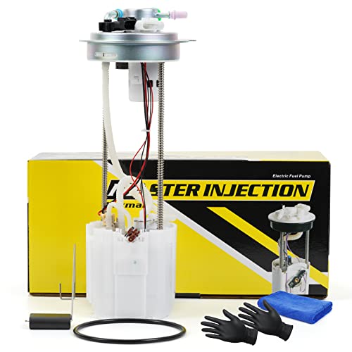
| FUEL PUMP | 15A | Mini Blade | In-tank Fuel Pump Motor, Level Sender Circuit |
| CRANK | 10A | Mini Blade | Starter Relay Coil, Clutch Start Switch (Manual) / PNP Switch |
| ETC | 15A | Mini Blade | Electronic Throttle Control Actuator Motor |
| COOL/FAN 1 | 40A | J-Case Cartridge | Electric Engine Cooling Fan Primary Speed Control Circuit |
| COOL/FAN 2 | 40A | J-Case Cartridge | Electric Engine Cooling Fan Secondary Speed Circuit |
| ABS | 60A | Maxi Fuse | Electronic Brake Control Module (EBCM) Pump Motor |
| STUD #1 | 40A | Maxi Fuse | Auxiliary Trailer Battery Feed, 7-Pin Harness RV Power |
| STUD #2 | 30A | Maxi Fuse | Trailer Brake Wiring Harness, Interior Utility Junction |
Instrument Panel (I/P) Fuse Block Circuit Assignment
| Cavity Number | Rating | Fuse Type | Protected Circuitry |
|---|---|---|---|
| CIG LTR (Fuse 13) | 15A | Mini Blade | Cigarette Lighter Socket, OBD-II Diagnostic Link Connector (DLC) Pin 16 |
| CLUSTER | 10A | Mini Blade | Instrument Panel Cluster (IPC), PRNDL Display, Stepper Motors |
| IGN 0 | 10A | Mini Blade | PCM Ignition Signal, Transmission Control Module Run Feed |
| TBC 2B | 15A | Mini Blade | Body Control Module (BCM) Logic and Memory Rail |
| RADIO | 15A | Mini Blade | Head Unit, Audio Amplifier, Remote CD Unit |
| 4WD | 15A | Mini Blade | Transfer Case Shift Control Module (TCCM), Dash Switch |
| AIRBAG | 15A | Mini Blade | Sensing and Diagnostic Module (SDM), Passenger Airbag Switch |
Underhood ISO Relay Block Identification
The underhood center incorporates several high-current ISO micro-relays that switch power directly from the main battery bus:
- Fuel Pump Relay: 4-pin mini-relay commanded by PCM Pin green-9 to pressurize the fuel rail.
- Starter Relay: Energized via the ignition switch in CRANK position through the neutral safety switch.
- A/C Compressor Relay: Switched by the PCM depending on high/low pressure switch continuity.
- Cooling Fan Relays (FAN 1, FAN 2, FAN 3): Three-relay array orchestrated by the ECU to run fans in series (low speed) or parallel (high speed) based on engine coolant temperature and A/C head pressure.
Never swap a high-current circuit relay with an accessory relay of lower contact capacity. Doing so risks terminal arcing, plastic housing deformation, and sudden circuit loss while operating the vehicle.
Check Engine Light Triggers and Powertrain Control Module Circuit Faults


Electrical issues on 2005 GMC Sierras often present as sensor failures or mechanical breakdowns when the root cause is actually an open fuse, broken circuit trace, or burned relay pin. Knowing how power distribution failures interact with your truck’s diagnostic architecture prevents costly, unnecessary parts replacement.
Diagnostic Port Failures and Scanner Communication Loss
Technicians frequently encounter a “No Link” or “Communication Error” on their hand-held scanners when trying to read a diagnostic code. On the 2005 Sierra, 12-volt battery power for Pin 16 of the Data Link Connector originates solely from the 15A CIG LTR fuse (Cavity 13) in the interior I/P fuse block. If an auxiliary device shorts out the dashboard cigarette lighter socket, this fuse opens instantly. This completely shuts down power to Pin 16, preventing the scanner from powering its transceiver and reading stored codes or clearing a lit check engine light, even though the truck still runs normally.


No-Crank and Stall Conditions from ECM B and IGN E Fuses


The ECM B (20A) fuse supplies constant unswitched battery voltage directly to the ECU/PCM memory rail and the heavy-current contact (Pin 30) of the fuel pump relay. When this fuse blows:
- The engine cranks over without starting because the in-tank pump receives zero electrical current.
- The fuel gauge drops entirely to empty on certain instrument clusters due to loss of reference ground return.
- The PCM cannot trigger the fuel injectors, leaving the plugs dry despite strong spark delivery.
Conversely, an open ECM 1 (10A) fuse cuts key-switched ignition voltage to the camshaft and crankshaft position sensors. This fault triggers an immediate stall or extended crank condition. It can easily be misdiagnosed as jumped timing chain teeth or an internal mechanical sensor failure. Furthermore, if the ENG 1 (10A) fuse fails, current drops to the heated oxygen sensor elements. This triggers trouble codes P0135, P0141, P0155, or P0161 along with an illuminated check engine light.
Coolant Flow Interruptions and Fan Relay Circuit Logic
The 2005 model year marked the transition to dual electric cooling fans across the 4.8L, 5.3L, and 6.0L Vortec platforms, replacing the traditional mechanical fan clutch. Controlled by three distinct relays (FAN 1, FAN 2, FAN 3) and protected by twin 40A J-Case fuses, this system manages coolant flow stabilization during severe duty cycles. If the 40A COOL/FAN 1 cartridge fuse blows, low-speed operation fails completely. Under heavy towing loads or slow idle conditions, engine temperatures climb rapidly, creating localized boiling and poor coolant flow through the cylinder heads while the PCM logs overheat flags.
Erratic Oil Pressure and Instrument Cluster Stepper Failures
The 2005 Sierra is notorious for faulty stepper motors on the instrument panel cluster. A sudden loss of the oil pressure reading, an oil pressure gauge pegged at 80 PSI, or a dead fuel gauge is often blamed on a bad oil pressure sending unit or blown CLUSTER fuse. However, a blown CLUSTER (10A) fuse shuts down the entire instrument panel, including the digital odometer and shift gear indicator (PRNDL). If only the oil pressure gauge behaves erratically while all other gauges sweep smoothly, the internal stepper motor or the rear engine-block sender sub-harness has failed, not the fuse block circuit.


Underhood fuse block primary feeder terminal studs (M8 nuts) require an OEM torque spec of 15 Nm (133 lb-in). Loose terminal connections create resistive heat that melts the lower fuse housing.
Step-by-Step Circuit Testing Using an OBD-II Scanner and Multimeter


Diagnosing suspected electrical problems systematically eliminates guesswork and avoids spreading female terminal pin receivers. Always follow this standardized five-step procedure when troubleshooting the GMT800 electrical platform.
- Establish Battery Reference Voltage and Check Data Link Communications
Connect an OBD-II scanner directly to the 16-pin DLC port beneath the steering column. Turn the ignition key to the ON/RUN position without cranking. If the scanner fails to illuminate or establish communication, grab your Digital Multimeter (DMM), clip the black lead to clean chassis metal, and touch the red probe to Pin 16 (bottom right terminal). You should see standard battery voltage (minimum 12.4V DC). If voltage reads zero, remove and test the 15A CIG LTR fuse in the instrument panel panel using a dedicated fuse puller tool. - Execute Closed-Circuit Voltage Drop Tests Across Blade Fuses
Do not immediately yank fuses out with pliers, as this bends the internal female socket terminals. Switch your DMM to millivolt (mV) DC mode. Turn the ignition switch to the ON position. Probe the two exposed metal test tabs on the back of each Mini Blade fuse without extracting it. A properly operating, active circuit shows a tiny millivolt drop (typically 0.5 to 4.5 mV depending on amperage load). A blown fuse shows the full source voltage (12.4V+) across its test points because current cannot jump the blown bridge. A completely dead circuit shows a flat 0.000 mV on both points, pointing to an upstream power disconnect. - Interrogate the Powertrain Control Module for Latent Diagnostic Codes
With the scan tool active, check for engine and transmission trouble codes. Codes such as P0601 through P0604 indicate internal ECU power supply rail issues. Trouble codes P0685 or P0689 point to poor primary ignition relay control circuits. If codes indicate an open circuit to multiple solenoids or sensors (like both downstream O2 heaters and the EVAP solenoid sharing codes simultaneously), cross-reference your findings with the ENG 1 and ECM 1 power traces in the underhood fuse box diagram. - Bench-Test and Inspect ISO Micro/Mini Relays
If a component like the fuel pump fails to activate, extract its relay using an insulated puller. Inspect the four or five copper spade terminals for signs of heat discoloration, pitting, or green oxidation. Check continuity across control terminals 85 and 86 using your meter’s resistance (ohms) scale. You should read between 70 to 110 ohms, representing the internal electromagnetic coil resistance. Next, connect 12-volt battery power and ground across pins 85 and 86. Listen for an audible snap, then verify 0.0 to 0.2 ohms resistance across load terminals 30 and 87 with your meter. - Verify Fuse Socket Contact Retention Tension
Repeated mechanical probing can deform the female leaf springs inside the plastic fuse housing, leading to high resistance and intermittent power cuts. Disconnect the truck battery. Using an individual spare fuse terminal blade or flat terminal gauge, slide it in and out of the fuse cavity. Feel for distinct mechanical drag. If the terminal fits loosely without friction, remove the lower block cover and reform or replace the female Metri-Pack terminal core.
2005 GMC Sierra Electrical Hazards, Torque Specs, and Wiring Pitfalls
Working on the 2005 Sierra’s wiring involves distinct model-year and platform hazards. Understanding these prevents component damage and dangerous fire risks.
The Danger of Over-Fusing Circuit Branches
Never install a higher-capacity fuse in place of an opened factory fuse (such as replacing a 15A Mini Blade with a 25A or 30A fuse to stop it from blowing). General Motors calculated the harness cross-sectional area (gauge) and insulation thermal limits to match each specific fuse rating. Over-fusing forces the factory wiring harness to act as the fusible link instead. This melts the wire insulation, shorts adjacent circuits within the factory loom, and can trigger dangerous under-dash electrical fires.
Platform Discrepancies: GMT800 vs. Early 2007 GMT900


The 2005 model year falls square in the late evolution of the GMT800 design cycle (1999–2006, and 2007 “Classic”). Be careful not to use electrical schematics from the redesigned 2007–2013 GMT900 Sierra platforms. The GMT900 models feature an integrated central junction center with internally soldered, non-serviceable printed circuit relays and an entirely different BCM data bus (high-speed GMLAN vs. the Class 2 serial data system used in your 2005 truck). A 2005 Chevrolet Silverado shares identical electrical architecture with the 2005 GMC Sierra, making Silverado fuse schematics directly interchangeable, but GMT900 diagrams will lead to serious wiring errors.
Chassis Ground Faults Mimicking Fuse Failures
A common mistake when diagnosing a 2005 Sierra is mistaking an open ground circuit for a blown fuse. The GMT800 platform relies heavily on exposed external ground studs:
- G103 / G104: Anchored to the lower front-engine structure near the timing chain cover and the rear of the cylinder heads. These ground the PCM, knock sensors, and spark banks.
- G110: Located on the driver-side frame rail beneath the cab door. Corroded connections here cause the fuel pump to lose its ground return, making the pump play dead even when the underhood FUEL PUMP fuse reads fully powered.
- G200 / G203: Located on the metal structure behind the dash kick panels. Corrosion here causes the instrument cluster to reboot intermittently.
Factory torque spec for engine block and chassis ground bolts (M10 fasteners) is 35 Nm (26 lb-ft). Smaller body-sheet ground ring bolts (M6 fasteners) require an OEM torque spec of 9 Nm (80 lb-in). Clean all mating surfaces to bare shiny metal before re-torquing.
2005 GMC Sierra Fuse Box Diagram Technical FAQ
Which fuse controls the OBD-II diagnostic port on a 2005 GMC Sierra?
Pin 16 battery power for the OBD-II diagnostic connector is supplied directly by the 15A CIG LTR fuse (Position 13), located in the interior Instrument Panel (I/P) fuse block on the driver-side dashboard end-cap. If an auxiliary accessory or phone charger shorts out the center console lighter socket, this fuse will blow. This cuts operating power to diagnostic scan tools, resulting in a scanner communication failure.
Why does my 2005 Sierra crank over normally but refuse to fire up?
A no-start condition with normal starter cranking usually points to an open 20A ECM B fuse or 15A FUEL PUMP fuse in the underhood electrical center. The ECM B fuse provides switched power to the fuel pump relay coil and sustains constant battery memory voltage to the Powertrain Control Module. If this fuse blows, the fuel pump will not run, leaving the fuel rail without injection pressure. An open 10A ECM 1 fuse will also produce a crank-no-start condition by cutting power to the crankshaft position sensor.
Can a blown fuse cause my ABS and brake warning lights to stay on?
Yes. The Electronic Brake Control Module (EBCM) relies on multiple power feeds within the underhood fuse center. High-current motor pump power flows through the large 60A ABS Maxi-Fuse, while internal logic and wheel speed sensor processing run through the 30A ABS fuse. If either fuse opens due to an internal pump motor short or ABS module circuit failure, the safety system completely disengages, illuminating both the ABS warning light and the red BRAKE light on the dash.
Are the fuse boxes identical between 2005 GMC Sierra 1500 and 2500HD models?
The main physical fuse box architectures are identical between 1500, 2500HD, and 3500 platform models within the 2005 model year. However, their internal circuit population varies slightly depending on the engine and transmission combination. Gas Vortec trucks (4.8L, 5.3L, 6.0L) use the dual electric fan positions (COOL/FAN 1 and 2), while 6.6L Duramax diesel and 8.1L big-block configurations utilize mechanical or heavy hydraulic engine cooling fans, leaving those specific fuse bays empty or repurposed for glow plug and fuel pre-heater sub-systems.