2011 Ram 1500 Fuse Box Diagram: Locations, Amperage, And Relay Functions
When your 2011 Ram 1500 experiences a sudden failure of the headlights, power windows, or ignition system, the solution is often found within a small plastic housing under the hood. For many truck owners, an electrical glitch can feel like a major mechanical breakdown, but more often than not, it is a simple matter of a compromised circuit protector. Locating and identifying the correct fuse or relay among the dozens of circuits in the Power Distribution Center can be a daunting task without an accurate diagram and professional guidance. This expert blueprint provides a detailed map of the 2011 Ram 1500 fuse box locations, amperage ratings, and relay functions to help you restore reliable electrical performance and maintain your vehicle’s trusted utility.
Identifying the 2011 Ram 1500 Fuse Box Locations and Housing
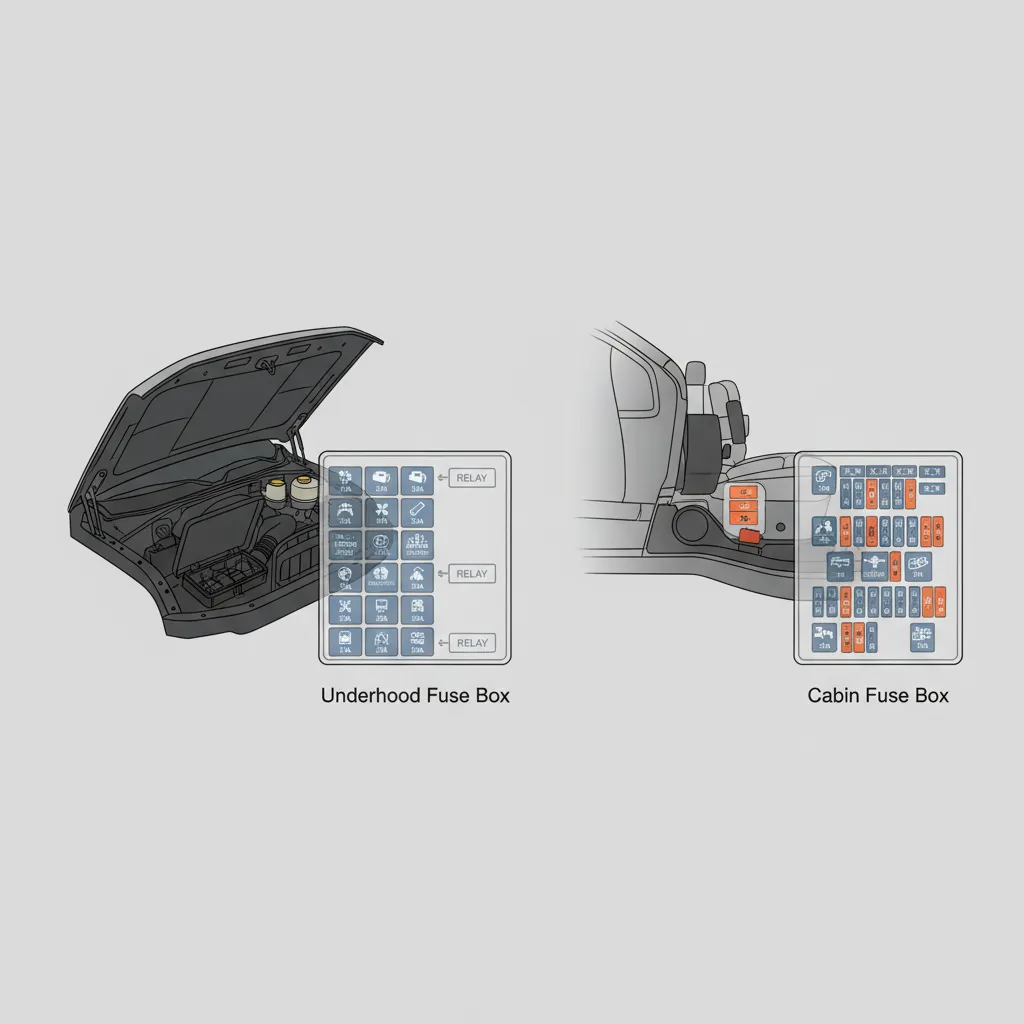
The 2011 Ram 1500 represents a pivotal era in truck design where electrical architecture shifted toward a centralized system. For the professional technician or the DIY enthusiast, this means you won’t be crawling under the dashboard or removing side panels to find blown fuses. Instead, Dodge (Ram) engineered the 1500 with primary circuit protection located entirely within the engine compartment to withstand high-temperature environments and provide complete accessibility for maintenance.
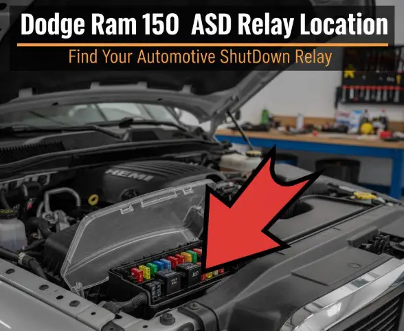
The Power Distribution Center (PDC) and IPM
The electrical heart of the vehicle is positioned on the driver’s side of the engine bay, situated directly behind the battery. This location consists of two primary modules housed together: the Power Distribution Center (PDC) and the Integrated Power Module (IPM). These units work in tandem to manage vehicle-wide electrical distribution, ranging from high-current engine functions to low-current interior electronics. To access these modules, you must release the locking tabs on the black protective plastic casing. In my experience, these tabs can become brittle over time due to heat cycles; always apply even pressure to avoid snapping the clips.
One of the most reliable ways to confirm your specific layout is to refer to the official guide provided by the manufacturer. While many 2011 models share a standard configuration, variations in trim levels—such as the ST, SLT, Laramie, or Sport—can introduce additional circuits for luxury or towing features. The consolidation of these components into a single under-hood location was a significant upgrade over older truck models, which often split fuses between the dash and the engine, complicating the diagnostic process.

2011 Ram 1500 Power Distribution Center (PDC) Diagram and Circuit Functions
The PDC is designed to handle the heavy lifting. This module primarily houses high-current fuses and relays that support the vehicle’s “muscle” systems. In professional terminology, this is where you find your J-Case fuses—square, high-amperage links designed to handle loads that would melt a standard mini-fuse. The PDC manages systems pulling up to 60 amps, requiring these specialized heavy-duty components.
High-Current Circuit Mapping
When diagnosing a vehicle that refuses to start or has massive lighting failures, the PDC is your first stop. Below are key technical mappings for this module:
- Starter Motor (F03/F04): Usually protected by a 30A or 40A J-Case fuse. If your battery is fully charged but the engine won’t turn over, this is the primary suspect.
- Alternator Sense (F01): A critical link that monitors charging system health.
- Cooling Fan Relay: Controls the electromechanical switch for the radiator fan, preventing engine overheating.
- Fuel Pump Relay: Vital for engine combustion; a failure here mimics a bad fuel pump.
Relays are electromechanical switches that allow a low-current signal (like turning your key) to control a high-current circuit (like the starter). If a fuse is intact but a system fails, try swapping the relay with a matching one from a non-critical system (like the horn) to test its function.
I recommend interpreting the printed diagram found on the underside of the PDC cover. It serves as an on-the-spot diagnostic tool that matches the physical layout of the box. If you find yourself in a scenario where a failed starter fuse prevents engine turnover despite a healthy battery, always check for signs of heat stress on the fuse terminals before replacing it.

Integrated Power Module (IPM) Layout for Interior and Accessory Circuits
While the PDC handles the high-voltage demands, the IPM (Integrated Power Module) is the comprehensive manager of your daily convenience and safety electronics. This part of the module contains over 40 individual circuit protection points catering to both luxury and utility options. If your radio suddenly goes silent or your power windows stop responding, the IPM is where the solution resides.
The IPM utilizes space-efficient Mini-Fuses and Micro-Fuses. It is responsible for critical safety systems, including the Instrument Cluster, Airbag System (SRS), and the Anti-lock Braking System (ABS) modules. Furthermore, the IPM communicates directly with the Body Control Module (BCM) to manage interior lighting dimming and delay sequences. A common repair scenario involves a non-responsive radio or power outlet caused by a blown 20A mini-fuse in the IPM—often triggered by a faulty phone charger or an overloaded 12V socket.
Professional Troubleshooting for Recurring Electrical Faults
When a fuse “keeps blowing,” it is no longer a simple maintenance task; it is a diagnostic red flag. Fuses are designed to protect circuits from overloads, and a blown fuse indicates a potential problem in the circuit it protects. Simply replacing the fuse without addressing the root cause will likely result in the fuse blowing again, or worse, damaging the wiring harness.
By The Numbers
J.D. Power Reliability Rating
Rank out of 19 Fullsize Trucks
Research indicates that electrical system issues are a commonly reported problem for vehicles in this age range. To troubleshoot effectively, follow these expert tips:
- Identify the Short: Distinguish between a temporary surge and a direct short-to-ground. If the fuse blows the instant the circuit is activated, you have a short.
- Use a Multimeter: Instead of pulling every fuse, use a digital multimeter or a non-intrusive test light to check for continuity across the small metal terminals on top of the fuse while it is still plugged in.
- Check for Parasitic Drain: If your battery dies overnight, you may have a parasitic drain. This can be identified by performing an amp draw test while pulling fuses one by one until the draw drops.
- Examine Trailer Wiring: Many trailer light malfunctions on the 2011 Ram can be traced back to a corroded 7-way plug shorting the IPM fuse.
If you’re unsure about diagnosing or repairing an electrical problem, consult a qualified automotive technician. Many 2011 models can develop issues within the “Totally Integrated Power Module” (TIPM) itself, which is a more complex internal failure that requires expert replacement rather than just a fuse swap.
Safe Fuse Replacement Protocol and Technical Precautions
Replacing a fuse seems simple, but doing it incorrectly can lead to catastrophic failure of the vehicle’s onboard computers. Before you open the PDC or IPM, ensure your truck is parked and the ignition is in the “OFF” position. For high-amperage PDC replacements, I strongly recommend disconnecting the negative battery terminal to prevent accidental arching.
📋
Step-by-Step Guide
Use the fuse puller tool located inside the fuse box cover. Gently pull the suspected fuse straight up. Inspect the metal filament inside the transparent housing; a broken or scorched filament confirms it is blown.
Always match the replacement fuse to the exact amperage rating of the original. Standard automotive fuses are color-coded (Blue=15A, Yellow=20A, Green=30A) to prevent errors.
Never substitute a higher amperage fuse for a lower one. Using a 30A fuse in a 15A circuit bypasses the protection. If a surge occurs, the wiring will melt or the BCM will fry before the fuse blows, potentially causing an electrical fire.
For high-quality replacement parts that meet OEM specs, technicians often turn to trusted suppliers to ensure circuit integrity. Furthermore, remember that some aftermarket accessories—such as LED light bars or high-power audio systems—may require the addition of inline fuses. Relying solely on the factory IPM to handle these extra loads can lead to premature module failure. If you are part of the broader Ram community, you will find that TIPM health and fuse maintenance are the two most discussed topics for keeping these 4th-generation trucks on the road.
In summary, the 2011 Ram 1500 utilizes a centralized under-hood layout for both the PDC and IPM modules. Correct amperage matching is critical to preventing damage to sensitive onboard computers and wiring harnesses. If you encounter recurring fuse failures, it indicates an underlying short circuit that requires professional diagnostic equipment. For further assistance, consult your vehicle’s specific owner’s manual or visit a trusted automotive technician to perform a full electrical system health check. By following this comprehensive guide, you can ensure your Ram remains a professional and reliable tool for years to come.
Frequently Asked Questions
Where is the fuse box located in my 2011 Ram 1500?
The 2011 Ram 1500 features a unified electrical center located in the engine compartment on the driver’s side. You will find the Power Distribution Center (PDC) and the Integrated Power Module (IPM) housed under a single black cover near the battery. There is typically no secondary fuse box located inside the cabin for this specific model year.
What does each fuse in the fuse box control?
Fuses are categorized by their location. PDC fuses generally control high-current components like the starter, fuel pump, and radiator fan. The IPM fuses manage accessory systems such as the radio, power seats, interior lights, and the instrument cluster. Each fuse is assigned a number (e.g., M1, M13) which corresponds to a specific function listed in the diagram on the cover’s underside.
How do I replace a blown fuse safely?
First, ensure the ignition is off and the key is removed. Open the fuse box cover and locate the blown fuse using the diagram. Use a fuse puller tool to remove the suspect fuse and inspect the internal metal filament for a break. Replace it only with a new fuse of the exact same amperage and color-coding to maintain circuit integrity.
What does it mean if a fuse keeps blowing repeatedly?
If a replacement fuse blows immediately or shortly after installation, it indicates a ‘hard short’ or an overloaded circuit. This is often caused by frayed wiring, a failing component (like a seized motor), or aftermarket accessories drawing too much current. Professional diagnostic tools are required to trace the short and prevent potential damage to the vehicle’s modules.
Can I use a higher amperage fuse if I don’t have the correct one?
No, you should never use a higher amperage fuse than what is specified by the manufacturer. Fuses are designed to be the ‘weak link’ that breaks to protect expensive wiring. Installing a higher amperage fuse allows more current to flow than the wires can handle, which can lead to overheating, melted harnesses, and vehicle fires.

![2021 Ram 1500 Battery Replacement: Specs & Expert Tips [2026]](https://truckguider.com/wp-content/uploads/2026/03/2021-ram-1500-battery-replacement-featured-768x403.webp)
![2007 Ram 1500 5.7 Hemi: Specs, Reliability & Common Issues [2026]](https://truckguider.com/wp-content/uploads/2026/03/2007-ram-1500-5-7-hemi-featured.webp)
![2007 Dodge Ram Headlights [2026]](https://truckguider.com/wp-content/uploads/2026/03/2007-dodge-ram-headlights-featured.webp)