6.6L Duramax Sensor Location Diagram: Complete Component Guide 2026

A 6.6 Duramax sensor location diagram must match the engine generation before you use it. LB7, LLY, LBZ, LMM, LML, and L5P engines share several sensor functions, but their physical locations and emissions hardware are not identical.
That difference matters most on crossover model years such as 2004, 2006, and 2007. The safest approach is to identify the engine by the eighth VIN digit, then follow the matching sensor locations below.

Prime for Young Adults — 6 Months Free
Students and 18–24s get six months of Prime free, then half price.
Start 6 Months FreeThis guide covers the main engine-management, intake, fuel, timing, temperature, and exhaust sensors used on Silverado HD and Sierra HD pickups from 2001 through 2026.
How To Identify Your 6.6 Duramax Generation
Recommended Best Deal Products


Check the eighth character of the VIN before looking for a sensor. The VIN is visible through the windshield on the driver-side dashboard and appears on the registration or title.
| Duramax Engine | Pickup Model Years | 8th VIN Digit | Key Sensor Era |
|---|---|---|---|
| LB7 | 2001 to early 2004 | 1 | Early common-rail system |
| LLY | Mid-2004 to 2005 | 2 | EGR and variable-geometry turbo |
| Revised LLY | 2006 | 2 | Electronics similar to LBZ |
| LBZ | 2006 to 2007 Classic | D | Revised common-rail controls |
| LMM | 2007.5 to 2010 | 6 | DPF aftertreatment added |
| LML | 2011 to 2016 | 8 | DEF and SCR system added |
| L5P | 2017 to 2026 | Y | New fuel and electronic architecture |
The 2006 LLY deserves special attention. Although it still uses VIN code 2, its hardware is much closer to the LBZ than the earlier 2004.5 to 2005 LLY.
For a full year-by-year identification reference, use our Duramax generations chart from LB7 to L5P.
12 Key 6.6 Duramax Sensors To Locate First
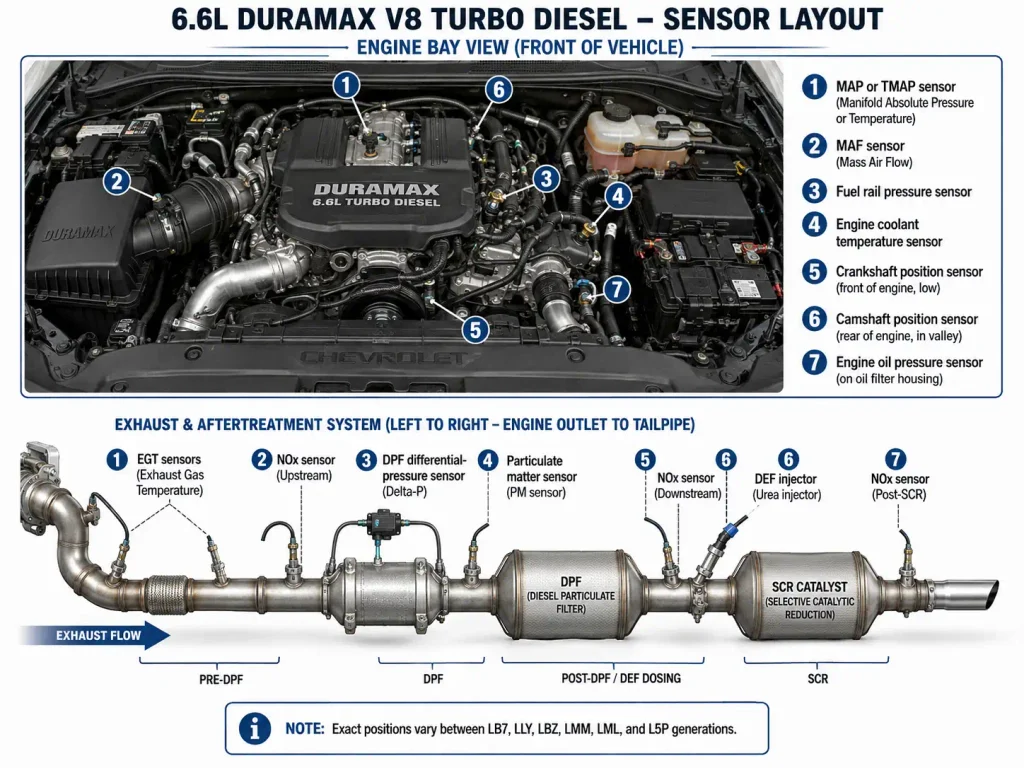
Most Duramax diagnostic work centers on a smaller set of engine-management sensors.
| Sensor | Abbreviation | Main Function | General Location |
|---|---|---|---|
| Manifold Absolute Pressure | MAP | Measures intake manifold pressure | Intake manifold or intake tube |
| Mass Air Flow | MAF | Measures incoming air mass | Air intake near air cleaner |
| Intake Air Temperature | IAT | Measures intake temperature | MAF or intake bridge depending on generation |
| Engine Coolant Temperature | ECT | Measures coolant temperature | Front or upper engine coolant passage |
| Crankshaft Position | CKP | Reports crankshaft speed and position | Engine front cover on early engines, rear block on L5P |
| Camshaft Position | CMP | Identifies camshaft position | Front cover on early engines, rear engine on L5P |
| Fuel Rail Pressure | FRP | Measures high-pressure fuel rail pressure | Fuel rail |
| Engine Oil Pressure | EOP | Monitors engine oil pressure | Engine block |
| Exhaust Gas Temperature | EGT | Monitors exhaust temperature | Exhaust aftertreatment system |
| DPF Differential Pressure | DPS | Measures pressure across DPF | Exhaust system with two pressure tubes |
| Nitrogen Oxides Sensor | NOx | Measures NOx before and after SCR | Exhaust system |
| Particulate Matter Sensor | PM | Monitors particulate emissions | Later exhaust aftertreatment systems |
The Manifold Absolute Pressure sensor measures pressure in the intake manifold. The Mass Air Flow sensor measures how much air enters through the intake.
These sensors may work together during boost, fueling, Exhaust Gas Recirculation, or EGR, and Diesel Particulate Filter regeneration calculations.
Where Are LB7 Duramax Sensors Located
The 2001 to 2004 LB7 has one of the simpler Duramax sensor layouts, but even the MAP sensor changed during this generation.
LB7 MAP Sensor
On a 2001 LB7, the MAP sensor is mounted on the right intake manifold.

Audible — Listen Free for 30 Days
One free credit a month and thousands of titles included.
Listen Free for 30 DaysOn 2002 through early 2004 LB7 engines, ATS documentation places the MAP sensor in the intake tube near the center of the engine.
That distinction is important if an aftermarket intake or Y-bridge has been installed.
LB7 Fuel Rail Pressure Sensor
The LB7 Fuel Rail Pressure sensor sits in the junction area between the two high-pressure fuel rails. ATS documentation for 2001 to 2004 trucks identifies the sensor in the junction block between the rail assemblies.
Look toward the center of the engine after removing the large intake resonator for better access.
LB7 Crank And Cam Sensors
Both the Crankshaft Position sensor and Camshaft Position sensor are associated with the front engine cover on the early Duramax architecture.
GM-based Duramax training material identifies both sensors on the front cover, with the CKP positioned lower and the CMP higher on the cover.
The CKP sends crank-speed and position information to the Engine Control Module, while the CMP helps the ECM determine cylinder position.
LB7 MAF Sensor
The MAF sensor is in the air-intake tract close to the air-filter housing. Follow the intake duct from the airbox toward the turbocharger to identify its electrical connector.
Audible Premium Plus — Annual Membership
12 audiobook credits up front, plus the full Audible catalogue.
See Annual PlansIf you are trying to identify left and right cylinder banks while tracing harnesses, our 6.6 Duramax cylinder number guide can help with engine orientation.
Where Are LLY LBZ And LMM Sensors Located
The LLY, LBZ, and LMM share several engine-bay reference points, but the LMM adds a Diesel Particulate Filter and more exhaust sensors.
LLY LBZ And LMM MAP Sensor
ATS specifies the MAP sensor on 2004.5 and later LLY, LBZ, and LMM engines on the intake tube above the alternator bracket.
A separate service reference for 2006 to 2010 trucks places it on the upper intake plenum to the passenger side of the alternator.
Those descriptions refer to the same general engine area.
LLY LBZ And LMM Fuel Rail Pressure Sensor
For 2004.5 and later LLY, LBZ, and LMM engines, the Fuel Rail Pressure sensor moved to the passenger-side fuel rail. ATS documentation clearly separates this layout from the LB7 junction-block design.
This location makes the generation change easy to recognize when comparing an LB7 with an LBZ or LMM.
LLY LBZ And LMM Intake Temperature Sensors
The primary intake temperature measurement is incorporated into the MAF sensor near the air-filter housing.
On 2006 through 2010 LLY, LBZ, and LMM applications, GM also uses a second IAT sensor in the intake manifold bridge under the turbocharger inlet mouthpiece.
This explains why a diagnostic code for IAT circuit 1 may lead you to a different connector than an IAT circuit 2 code.
LMM DPF Sensors
The LMM was the first pickup Duramax generation to add a factory DPF system.
The exhaust layout uses:
- EGT Sensor 1 before the Diesel Oxidation Catalyst
- EGT Sensor 2 farther downstream around the catalyst and filter assembly
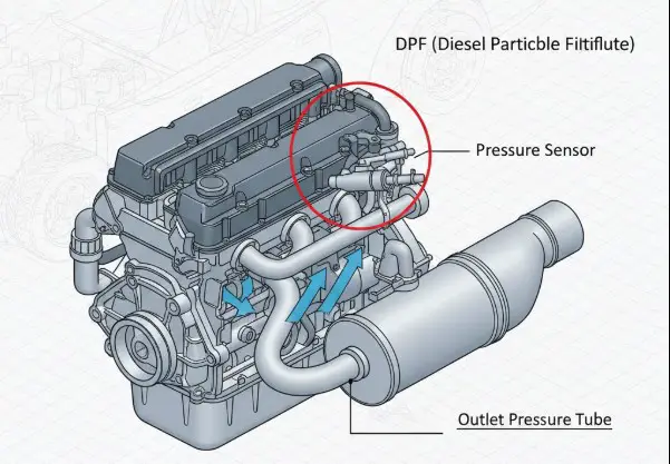
- DPF Differential Pressure sensor connected by pressure lines before and after the filter
GM documentation explains that the differential-pressure sensor measures the pressure difference across the DPF so the ECM can estimate soot loading and control regeneration.
Do not look for LML-style DEF or SCR sensors on a factory LMM pickup. Selective Catalyst Reduction and Diesel Exhaust Fluid arrived with the next generation.
Where Are LML Duramax Sensors Located
The 2011 to 2016 LML needs two diagrams for accurate troubleshooting. One should cover the engine bay, while the second should follow the exhaust aftertreatment system under the truck.
LML MAP Sensor
The LML MAP sensor is installed in the intake manifold. Service equipment instructions for 2011 to 2016 LML engines direct technicians to remove the MAP sensor from the intake manifold during induction-system service.
Because EGR gases pass through the intake system, soot buildup around this sensor can affect the passage exposed to manifold pressure.
For a deeper explanation of MAP and boost-sensor differences, see our boost pressure sensor location guide.
LML Fuel Rail Pressure Sensor
The LML Fuel Rail Pressure sensor is mounted at the rear of the left, or driver-side, fuel rail.
GM service information describing the LML high-pressure fuel system places the FRP sensor at the rear of the left rail. Technical installation documentation confirms the same location.
This is different from the passenger-rail location used on the preceding LLY, LBZ, and LMM layouts.
LML EGT And NOx Sensors
The LML introduced Selective Catalyst Reduction, or SCR, and Diesel Exhaust Fluid, or DEF.
A GM exhaust-system diagram identifies the main under-truck sequence as:
- NOx Sensor 1 near the front of the exhaust after the turbo downpipe
- EGT Sensor 1
- Hydrocarbon injector
- Diesel Oxidation Catalyst
- EGT Sensor 2
- DEF reductant injector
- Selective Catalyst Reduction catalyst
- NOx Sensor 2
- EGT Sensor 3
- Diesel Particulate Filter
- EGT Sensor 4 farther downstream
The DPF Differential Pressure sensor uses pressure tubes to compare exhaust pressure across the filter.
If you are replacing an LML EGT or NOx sensor, identify it by sensor number and position in the exhaust stream before loosening anything.
Where Are L5P Duramax Sensors Located
The 2017 through 2026 L5P uses a substantially revised electronic and fuel system. It should not be diagnosed using an LML engine-bay diagram.
L5P MAP And TMAP Sensors
On 2017 through 2022 L5P trucks, the temperature and manifold-pressure sensor is mounted on top of the intake manifold.
Banks installation documentation identifies the four-pin TMAP connector on top of the L5P manifold, with the Fuel Rail Pressure connection immediately nearby.
Late 2023.5 through 2026 trucks changed this arrangement. These engines use two related manifold sensors, and the lower pressure sensor sits farther down the intake manifold near the EGR valve.
That change makes a 2017 L5P diagram unsuitable as a precise MAP reference for a 2024 or 2026 truck.
L5P MAF Sensor
GM’s 2026 electrical component list places the Mass Air Flow sensor at the left front of the engine compartment, mounted to the air-cleaner lid.
It remains one of the easiest L5P sensors to identify visually because it sits directly in the fresh-air intake path.
L5P Fuel Rail Pressure Sensor
The L5P Fuel Rail Pressure sensor is at the top of the engine on the fuel rail.
GM’s Silverado HD electrical component list specifies that location. Banks documentation further identifies the FRP connection directly behind the top-mounted MAP or TMAP area.
L5P Coolant And Oil Pressure Sensors
For the 2023 L5P, GM places the Engine Coolant Temperature sensor at the top left front of the engine, beside the water outlet housing.
The Engine Oil Pressure sensor is at the front center area, mounted to the left side of the engine block.
These landmarks are more reliable than trying to identify a sensor by connector color alone.
L5P Crank And Cam Sensors
The L5P changed the familiar early-Duramax timing-sensor layout.
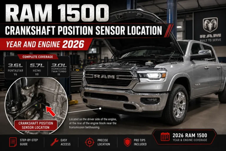
GM identifies the Crankshaft Position sensor at the left rear of the engine block behind the starter motor.
The Camshaft Position sensor is at the rear center of the engine, mounted on the right rear side of the block above the transmission bellhousing.
Do not use an LB7 through LMM front-cover diagram to locate these sensors on an L5P.
L5P Exhaust Sensors
GM’s L5P emissions architecture includes significantly more monitoring hardware than the early Duramax engines.
The system includes:
- Five Exhaust Gas Temperature sensors
- Two NOx sensors
- DPF Differential Pressure sensor
- Particulate Matter sensor
- DEF pressure sensor
- DEF level sensor
- DEF temperature sensor
- DEF quality sensor
GM’s L5P service bulletin shows these components distributed around the close-coupled catalyst, Diesel Oxidation Catalyst, DPF, SCR catalyst, and DEF system.
The exact exhaust hardware can also change within the L5P run. For example, 2024 through 2026 trucks use a later exhaust pressure arrangement that differs from 2017 through 2023 versions.
How To Match Duramax Sensors To Common DTCs
A sensor-related diagnostic trouble code identifies a circuit or operating condition. It does not prove that the sensor itself has failed.
| DTC | Main Circuit To Inspect | First Location To Check |
|---|---|---|
| P0101 | MAF performance | Air intake and MAF connector |
| P0106 | MAP performance | MAP sensor and intake passage |
| P0113 | IAT circuit high | MAF or IAT 1 circuit |
| P0098 | IAT 2 circuit high | Secondary intake temperature sensor where equipped |
| P0191 | Fuel rail pressure performance | FRP sensor and fuel-pressure system |
| P0335 | Crankshaft position circuit | CKP connector and harness |
| P0340 | Camshaft position circuit | CMP connector and harness |
| P2453 | DPF pressure circuit performance | Differential-pressure sensor and hoses |
| P2201 | NOx sensor performance | Upstream NOx sensor circuit |
| P229F | NOx sensor 2 performance | Downstream NOx sensor circuit |
Check the connector, wiring, reference voltage, grounds, sensor passage, and related mechanical system before ordering a replacement.
A clogged MAP passage, damaged harness, split DPF pressure hose, fuel-pressure problem, or exhaust leak can create symptoms that look like a failed sensor.
How To Locate A Duramax Sensor Safely
Use this process before unplugging an unfamiliar connector.
- Identify the Duramax generation. Check the eighth VIN digit rather than relying only on model year.
- Record every DTC. Do not clear codes until you have saved the diagnostic information.
- Let the engine and exhaust cool. EGT, NOx, DPF, and turbo-area components operate at very high temperatures.
- Use physical landmarks. Find the air cleaner, alternator, fuel rail, water outlet, turbocharger, DPF, or transmission bellhousing first.
- Compare the connector. Count pins and verify lock-tab shape before disconnecting it.
- Inspect the wiring. Look for rubbed insulation, heat damage, corrosion, loose locks, or broken harness clips.
- Follow the service procedure before removing the sensor. Fuel-rail and exhaust sensors require different handling from intake sensors.
Banks instructs L5P owners to disconnect the battery grounds before separating engine-sensor connectors because disconnecting sensors with the ECM powered can set diagnostic codes.
The same battery-disconnection rule should not automatically be treated as the removal procedure for every sensor on every generation. Follow the service instructions for the exact component being serviced.
Quick 6.6 Duramax Sensor Location Reference
This table works as a locator. Use the generation-specific sections above before removing any component.
| Sensor | LB7 | LLY | LBZ | LMM | LML | L5P |
|---|---|---|---|---|---|---|
| MAP | 2001 right intake manifold, 2002 to 2004 center intake tube | Intake tube above alternator area | Upper intake near alternator | Upper intake near alternator | Intake manifold | Intake manifold, revised dual arrangement on late 2023.5+ |
| MAF | Intake duct near airbox | Intake duct near airbox | Intake duct near airbox | Intake duct near airbox | Intake tract near airbox | Air-cleaner lid |
| CKP | Front engine cover | Front cover architecture | Front cover architecture | Front cover architecture | Front engine area | Left rear block behind starter |
| CMP | Front engine cover | Front cover architecture | Front cover architecture | Front cover architecture | Front engine architecture | Right rear block above bellhousing |
| FRP | Junction between rails | Passenger fuel rail | Passenger fuel rail | Passenger fuel rail | Rear of driver-side rail | Top fuel rail near MAP area |
| ECT | Front upper cooling area | Front upper cooling area | Front upper cooling area | Front upper cooling area | Front cooling passage area | Top left front near water outlet |
| DPF Pressure | Not equipped on pickup | Not equipped | Not equipped | DPF system | DPF system | DPF system |
| NOx Sensors | Not equipped | Not equipped | Not equipped | No SCR NOx pair | Two sensors | Two sensors |
| EGT Sensors | Limited emissions configuration dependent | Emissions configuration dependent | Emissions configuration dependent | DPF monitoring | Four primary exhaust positions in GM diagram | Five sensors in GM L5P architecture |
| PM Sensor | Not equipped | Not equipped | Not equipped | Not part of early system | Application dependent | Exhaust aftertreatment system |
Pickup applications are the focus of this chart. Vans, medium-duty trucks, chassis cabs, LGH, and L5D applications can use different calibrations or component layouts.
Maintenance specifications also vary by Duramax generation. If you are servicing the engine at the same time, our Duramax oil capacity chart by year covers LB7 through L5P specifications.
Which Duramax Sensor Diagram Should You Use
Use a 6.6 Duramax sensor location diagram that matches the engine RPO code, not just the truck’s model year.
An LB7 or LBZ owner will spend most diagnostic time around engine-bay sensors. An LMM adds DPF hardware, while LML and L5P trucks require a second diagram covering the complete exhaust aftertreatment system.
For 2017 through 2026 L5P trucks, check the exact model year again before locating intake sensors. The late 2023.5 sensor arrangement changed enough that an earlier L5P diagram can point you toward the wrong manifold connector.
Identify the engine, match the sensor name and DTC, locate it using fixed engine landmarks, then test the circuit before replacing parts.
5 Common Questions About Duramax Sensor Locations
Where Is The MAP Sensor On A 6.6 Duramax?
The location depends on generation. A 2001 LB7 places it on the right intake manifold, 2002 to 2004 LB7 engines use the center intake tube, LLY through LMM place it around the upper intake near the alternator, while LML and L5P use intake-manifold locations. Late 2023.5+ L5P trucks have a revised dual-sensor arrangement.
Where Is The Crankshaft Position Sensor On A Duramax?
Early Duramax training material locates the CKP at the front engine cover. The L5P is different, with GM listing the sensor at the left rear of the engine block behind the starter.
Where Is The Fuel Rail Pressure Sensor On A Duramax?
LB7 engines use a sensor around the junction between the fuel rails. LLY, LBZ, and LMM engines move it to the passenger rail, while the LML places it at the rear of the driver-side rail. The L5P sensor is on the top fuel rail near the manifold pressure-sensor area.
How Many EGT Sensors Does A 6.6 Duramax Have?
There is no single number for every Duramax. LMM, LML, and L5P emissions systems use different Exhaust Gas Temperature layouts, with GM’s L5P architecture showing five EGT sensors.
Are LML And L5P Sensor Locations The Same?
No. The L5P changed the fuel, intake, timing, and emissions architecture. One clear example is the Camshaft Position sensor, which GM locates at the rear of the L5P engine above the transmission bellhousing rather than using the older front-cover layout.