Dodge Ram 1500 Hemi Diagram: Essential System Guide
The 2012 Dodge Ram 1500 Hemi diagram provides a complete overview of the 5.7L engine configuration and various chassis systems. It helps owners identify the layout of essential parts like the fuel system, electrical harness, and cooling structure to simplify maintenance and streamline any complex mechanical repairs or troubleshooting tasks.
📌 Key Takeaways
- Visualizes the 5.7L Hemi engine and chassis layout.
- Helps identify critical sensors and hose routing.
- Always disconnect the battery before working on electrical systems.
- Use the diagram to verify fuse box and wiring locations.
- Essential for diagnosing overheating or electrical failures.
When you are working under the hood of a 2012 dodge ram 1500 hemi, having a clear and accurate diagram is not just a convenience—it is a necessity for ensuring the longevity and performance of your vehicle. The 5.7-liter V8 Hemi engine is a sophisticated piece of engineering that blends traditional muscle with modern technology like the Multi-Displacement System (MDS) and Variable Camshaft Timing (VCT). Understanding how these components interact within the overall system layout is crucial for any DIY enthusiast or professional technician. This article provides a detailed blueprint of the engine’s configuration, offering a comprehensive overview of its mechanical structure, electrical layout, and fluid systems. By following this guide, you will learn how to interpret complex schematics and apply that knowledge to real-world maintenance and repair tasks.
Comprehensive System Overview and Component Layout
The 2012 dodge ram 1500 hemi features an engine architecture that is both robust and complex. At its core, the 5.7L Hemi is a 90-degree V8 engine with a cast-iron block and aluminum alloy cylinder heads. The term “Hemi” refers to the hemispherical shape of the combustion chambers, though modern versions utilize a more complex global combustion chamber design to improve efficiency and reduce emissions. The diagram of this engine provides a visual breakdown of several integrated systems that must work in perfect harmony.
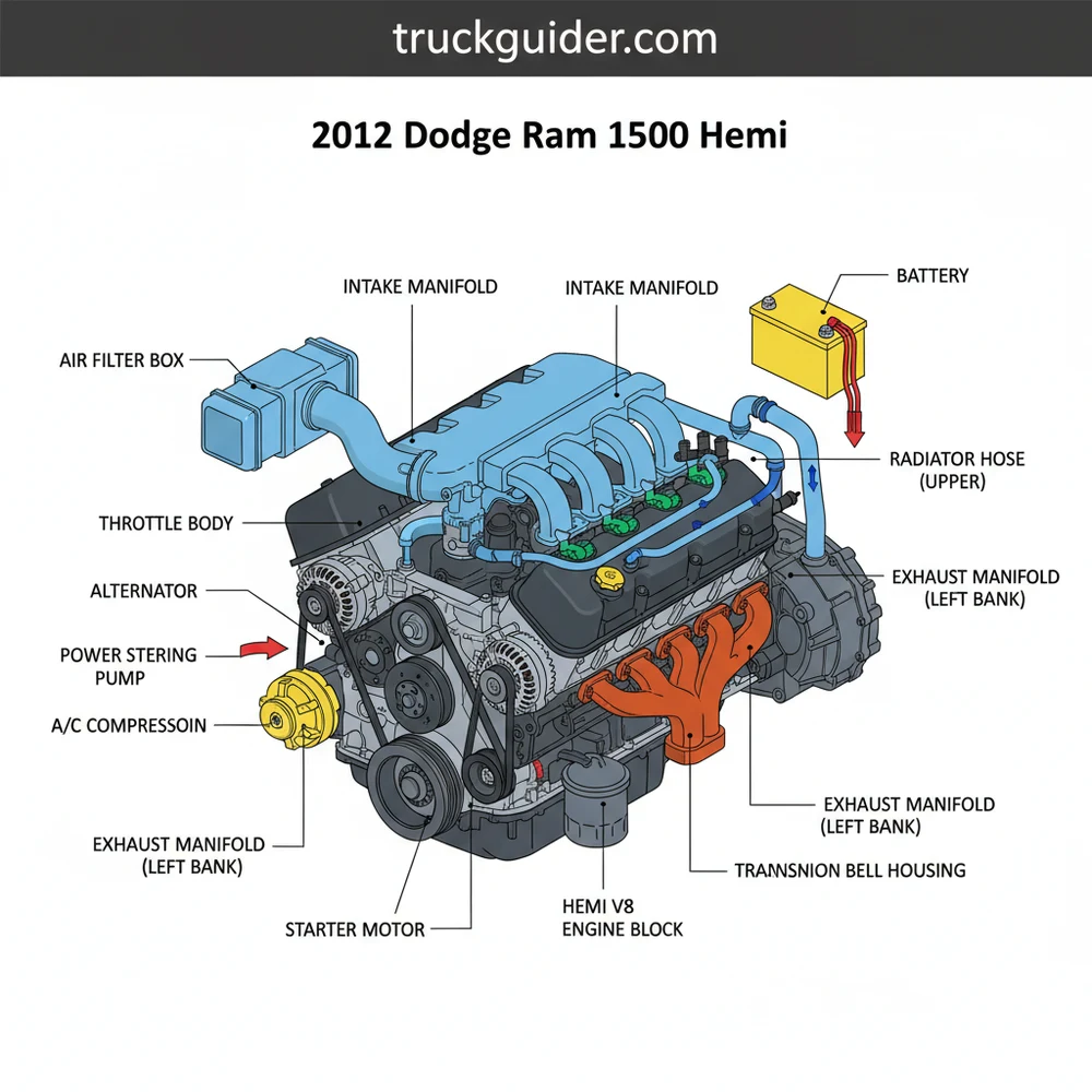
The primary structure is defined by the deep-skirt engine block, which provides exceptional rigidity for the crankshaft. When viewing a top-down layout of the engine, the intake manifold dominates the center, flanked by the two cylinder heads. Each head contains two spark plugs per cylinder, a unique configuration in the automotive world designed to ensure complete combustion and reduced exhaust emissions. This dual-ignition system is a critical component of the engine’s blueprint and is often a point of confusion for those new to the platform.
The front of the engine, often referred to as the Front End Accessory Drive (FEAD), is where the serpentine belt coordinates the movement of the alternator, water pump, power steering pump, and air conditioning compressor. The schematic for this area is vital for anyone attempting a belt replacement or diagnosing a pulley-related noise. Furthermore, the 2012 model includes a sophisticated cooling system configuration. This involves a heavy-duty radiator, a mechanical fan (often paired with an electric assist fan in certain towing packages), and a series of hoses that manage the thermal load of the high-output V8.
Internal to the block, the layout includes the MDS solenoids, which are situated in the “valley” of the engine beneath the intake manifold. These components are responsible for deactivating four of the eight cylinders during light-load cruising to save fuel. Understanding the spatial relationship between the intake manifold, the fuel rails, and these solenoids is essential for top-end engine repairs. The lubrication system also follows a specific schematic, utilizing a high-volume oil pump driven by the crankshaft to ensure that the VCT phasers and MDS lifters receive constant hydraulic pressure.
Top-Down Schematic of the 2012 Dodge Ram 1500 5.7L Hemi Engine highlighting the Intake Manifold, Serpentine Belt Path, Ignition Coil Packs, and Fluid Reservoirs.
The 2012 Hemi utilizes a 16-spark plug system. When referencing an ignition diagram, ensure you are tracking both the primary and secondary plug wires for each cylinder to avoid cross-firing or misfire codes.
How to Read and Interpret the Engine Blueprint

Interpreting a technical diagram for the 2012 dodge ram 1500 hemi requires a systematic approach. These schematics often use specific symbols and color-coding to represent different fluid types, electrical voltages, or mechanical connections. To use these diagrams effectively for installation or troubleshooting, follow these structured steps:
1. Establish Your Orientation: Before diving into the details, determine the orientation of the diagram. Most engine blueprints are drawn from the perspective of someone standing at the front bumper looking toward the windshield (front-view) or from directly above the engine bay (top-view). Locate the radiator at the “front” and the firewall at the “rear” to ground your perspective.
2. Identify the Serpentine Belt Configuration: One of the most common uses for a diagram is belt routing. On the 2012 Hemi, the belt path is intricate. Locate the tensioner pulley on the diagram—this is your starting point for releasing pressure. Follow the lines representing the belt as they wrap around the “grooved” pulleys (like the alternator and AC compressor) and the “smooth” idler pulleys.
3. Trace the Ignition and Wiring Harness: For electrical diagnostics, look for the central wiring trunk. On the 2012 model, the harness typically runs along the fuel rails. The schematic will show “branches” leading to each of the eight coil packs. Note that each coil pack has two outputs. Use the diagram to verify that the wires are leading to the correct cylinders (1-3-5-7 on the driver’s side and 2-4-6-8 on the passenger side).
4. Locate Fluid Pathways: Cooling and oiling diagrams use specific line weights or colors. Blue or green lines usually indicate coolant flow, while red or black lines indicate high-pressure oil or fuel. Trace the upper and lower radiator hoses on the schematic to understand how coolant enters the thermostat housing and exits through the water pump.
5. Identify the Multi-Displacement System (MDS) Components: If you are troubleshooting a “Hemi Tick” or fuel economy issues, find the section of the diagram labeled for the valvetrain. Look for the four MDS solenoids. The blueprint will show their location in the engine valley, which requires the removal of the intake manifold to access.
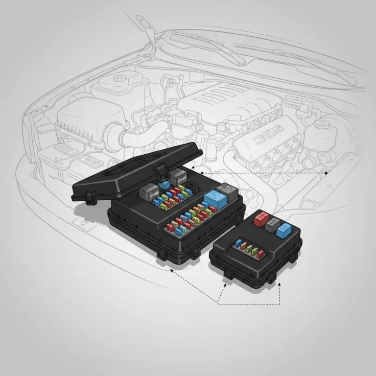
6. Cross-Reference with the Fuse Box (TIPM): The Totally Integrated Power Module (TIPM) acts as the brain for the engine’s electrical system. A comprehensive diagram of the 2012 Ram will include a pinout or layout of this box, located on the driver’s side fender. Match the fuse numbers on the diagram to the physical box to test circuits for the fuel pump, ignition coils, or cooling fans.
7. Verify Torque Specifications: A high-quality diagram or schematic often includes torque sequences, especially for the cylinder heads or intake manifold. Always follow the numbered sequence (usually starting from the center and spiraling outward) to ensure even clamping force and prevent gasket leaks.
When using a diagram to replace the serpentine belt, use a piece of chalk or a marker to draw the path on the radiator shroud if the factory sticker is missing. This provides a quick physical reference that matches your blueprint.
Common Issues and Diagram-Based Troubleshooting

The 2012 dodge ram 1500 hemi is a workhorse, but it is prone to specific issues that are much easier to solve when you have a diagram in hand. One of the most frequent complaints is the “Hemi Tick.” Using a mechanical layout diagram, owners can identify that this sound often originates from either broken exhaust manifold bolts or a failing lifter. By referencing the exhaust system schematic, you can pinpoint which cylinders are most likely to have broken bolts (usually the rear-most cylinders, 7 and 8) due to heat expansion.
Another common issue involves the MDS system. If the truck feels like it is “shuddering” when switching between 4-cylinder and 8-cylinder modes, the diagram helps you locate the MDS solenoids and the oil pressure sensor. Because the MDS relies on oil pressure to collapse the lifters, a schematic of the oiling system can show you if a blockage in the small oil passages is the culprit.
Never attempt to diagnose electrical issues without first disconnecting the battery. The 2012 Ram’s TIPM system is sensitive to voltage spikes, and a short circuit while probing a connector can lead to an expensive module replacement.
The cooling system is another area where the diagram proves invaluable. The 2012 model can suffer from water pump leaks or thermostat failures. By viewing the cooling system layout, you can see how the bypass hose connects to the water pump, which is a common site for slow leaks that are hard to see from above. If the engine is overheating, the blueprint allows you to verify that the belt is spinning the water pump in the correct direction—a common mistake during DIY belt installations.
Tips and Best Practices for Maintenance
Maintaining the 2012 dodge ram 1500 hemi requires attention to detail and the use of high-quality components. To keep your engine running according to its original blueprint, consider these best practices:
- ✓ Use the Correct Oil Weight: The MDS system on the 5.7L Hemi is extremely sensitive to oil viscosity. Always use 5W-20 oil as specified in the owner’s manual. Using a heavier oil like 10W-30 can prevent the MDS solenoids from functioning, leading to “limp mode” or check engine lights.
- ✓ Spark Plug Intervals: The 2012 Hemi uses nickel-plated spark plugs that should be changed every 30,000 to 50,000 miles. Because there are 16 plugs, it is easy to lose track. Use your ignition diagram to check off each cylinder as you complete it.
- ✓ Monitor the PCV Valve: The Positive Crankcase Ventilation (PCV) valve is located on the back of the intake manifold. It is often overlooked because it is hard to see. Referencing your component layout will show you its exact position; replacing this every 50,000 miles can prevent oil consumption issues.
- ✓ Inspect Exhaust Manifolds: Periodically check the rear exhaust manifold heat shields for looseness. If you see a gap, the bolts may have already snapped. Early detection using a layout guide can save you from a more difficult extraction job later.
- ✓ Keep the TIPM Dry: Ensure the cover of your fuse box (TIPM) is always snapped tight. Moisture intrusion is the number one cause of “ghost” electrical issues in 2012 Rams.
When purchasing replacement parts, always cross-reference the part numbers with the diagram’s specifications. For example, the 2012 Hemi has two different alternator options (160-amp or 180-amp). Checking your vehicle’s configuration against the electrical blueprint ensures you don’t install an underpowered unit that could strain the battery.
Cost-saving can be achieved by performing your own fluid changes and bolt-on repairs, but never skimp on the quality of sensors. The Hemi engine’s computer system is designed to work with Mopar-spec sensors. Using cheap aftermarket oxygen sensors or cam/crank sensors often leads to erratic idling and poor fuel economy because their voltage curves don’t perfectly match the factory schematic.
Summary of the Hemi System Layout
Mastering the 2012 dodge ram 1500 hemi requires a combination of mechanical intuition and technical resources. By studying the component structures and layout configurations provided in a detailed diagram, you move from guesswork to precision. Whether you are identifying the path of the serpentine belt, locating the 16 spark plugs, or troubleshooting the complex MDS system, the schematic serves as your ultimate roadmap.
The 5.7L Hemi is a legendary engine for a reason—it offers a balance of power and reliability that few other V8s can match. However, that performance is dependent on every part of the system functioning exactly as the blueprint intended. Regular maintenance, such as using the correct 5W-20 oil and keeping the cooling system in peak condition, ensures that the physical engine continues to match its design specifications. By utilizing the troubleshooting tips and best practices outlined here, you can confidently handle the upkeep of your 2012 dodge ram 1500 hemi, keeping it on the road and performing at its best for hundreds of thousands of miles. Remember, the key to a successful repair is not just having the right tools, but having the right information before you even pick them up.
Step-by-Step Guide to Understanding the Dodge Ram 1500 Hemi Diagram: Essential System Guide
Identify the specific system you need to repair within the overall Dodge Ram 1500 Hemi diagram.
Locate the primary component and its surrounding connections to ensure clear access during the removal process.
Understand how the wiring or hose routing is organized within the engine bay structure.
Apply the correct torque specifications and routing paths as shown in the system configuration guide.
Verify that all electrical connectors and mechanical fasteners are securely seated before testing the engine.
Complete the repair by clearing any fault codes and performing a brief test drive to ensure stability.
Frequently Asked Questions
Where is the engine oil pressure sensor located?
The engine oil pressure sensor is located on the back of the Hemi engine block, near the top of the camshaft. It is usually behind the intake manifold, making it a bit difficult to reach without proper tools, but identifying it on the system layout is the first step for replacement.
What does this Hemi diagram show?
The Dodge Ram 1500 Hemi diagram shows the complex layout of the 5.7L V8 engine, including fuel injection, cooling, and electrical systems. It serves as a visual map for locating every major component and understanding how the overall vehicle structure integrates different mechanical parts for optimal performance.
How many wires does the Hemi MAP sensor have?
Most sensors in the Hemi engine configuration use a standard three-wire setup, including a 5-volt reference, signal return, and ground wire. However, larger components like the alternator or starter motor feature heavier gauge battery cables to handle the significant current required for the vehicle’s electrical system.
What are the symptoms of a bad Hemi component?
Symptoms of a bad Hemi component often include rough idling, decreased fuel efficiency, or a check engine light. If the MDS system fails, you might notice vibration or hesitation. Using a diagram helps you pinpoint if the issue stems from a faulty component or a damaged wiring harness.
Can I replace Hemi components myself?
Yes, many repairs on the Ram 1500 can be done yourself using a clear diagram. While internal engine work is complex, replacing external components like the alternator, water pump, or spark plugs is straightforward for those with basic mechanical skills and the right layout guide for reference.
What tools do I need for Hemi repairs?
You will typically need a standard metric socket set, torque wrench, and screwdrivers for most tasks. A diagnostic OBD-II scanner is also essential for reading fault codes, while a multimeter helps verify that electrical connections within the system configuration are functioning correctly before starting any teardown.

![2005 Dodge Ram 1500 Lug Pattern, Bolt: Full Specs & Data [2026]](https://truckguider.com/wp-content/uploads/2026/03/featured-9791c354-768x768.webp)


![Best Air Bags for RAM 2500 Coil Springs: Full Specs & Data [2026]](https://truckguider.com/wp-content/uploads/2026/03/air-bags-for-ram-2500-with-coil-springs-featured.webp)