Dodge Ram Headlight Wiring Diagram: Circuit Identification And Electrical Troubleshooting
For a Dodge Ram owner, a clear view of the road ahead is dependent on a complex network of wires, relays, and modules that must work in perfect harmony. When a headlight fails or an upgrade is planned, the lack of a reliable wiring diagram can turn a simple fix into a frustrating diagnostic nightmare. Whether you are dealing with a flickering bulb on a 4th Gen or trying to rewire an older 2nd Gen workhorse, understanding the electrical architecture is non-negotiable. This expert guide provides a professional breakdown of Dodge Ram headlight wiring, teaching you how to decode schematics, troubleshoot with precision, and safely integrate aftermarket components while maintaining the integrity of your vehicle’s factory systems.
Decoding a Dodge Ram Headlight Wiring Diagram: Symbols and Color Codes
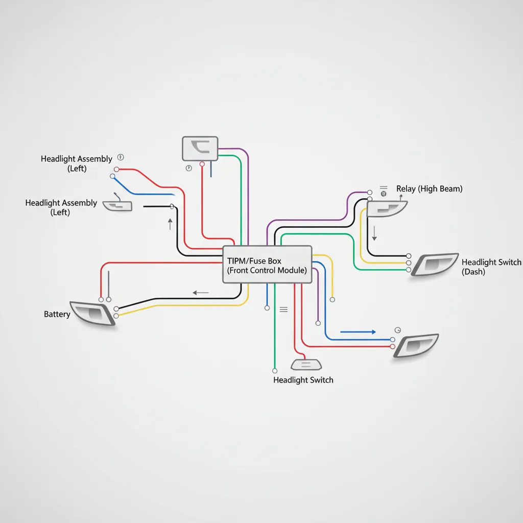
The first step in any successful electrical repair is the ability to read the comprehensive roadmap provided by the manufacturer. Automotive schematics use standardized symbols to represent complex components. In a Dodge Ram, you will frequently encounter symbols for ground points (indicated by a series of parallel lines of decreasing width), fuses (represented by a wavy line inside a rectangle), and multi-filament bulbs which show two distinct wire coils within a single glass housing.
Dodge-Specific Color Coding Conventions
While color codes can shift between generations, Chrysler/Stellantis has maintained certain conventions that are reliable for identification. For many late-model Rams, you will find White/Dark Blue wires serving the high beams and White/Tan wires for the low beams. Ground wires are almost universally solid Black or Black/Light Green. Misidentifying these is a common pitfall; a DIYer might mistake a solid black ground wire for a signal wire when attempting to tap into a circuit for a light bar. If a 12V power source is mistakenly bridged to a ground wire, it will cause an immediate short circuit, potentially damaging the expensive Totally Integrated Power Module (TIPM).
Power Distribution and Logic
It is vital to distinguish between constant 12V power and switched signals. In older models, the headlight switch directly handled the current. In modern Rams, the switch sends a low-voltage signal to the Body Control Module (BCM), which then instructs the TIPM to send power to the lamps. Research indicates that standard halogen bulbs operate on a 12-volt system, but even a minor voltage drop of 10% due to high resistance or poor wiring can lead to a 30% reduction in light output, making the vehicle less safe during night driving.
Before testing any wire, verify the color code at the TIPM connector. Colors can fade over time due to engine heat, turning a “White/Tan” wire into a generic yellowish hue that is easy to misidentify.
Navigating Year-Specific Variations in Dodge Ram Headlight Circuits
One of the most significant challenges for Ram owners is the massive shift in electrical architecture over the last two decades. A 2001 Ram 1500 uses a relatively trusted analog system where relays and fuses do the heavy lifting. In contrast, a 2019 Ram 1500 utilizes a complex complete guide of digital logic where the computer monitors every milliamp of current.
The Transition to Pulse Width Modulation (PWM)
Starting around 2006, Dodge began implementing Pulse Width Modulation (PWM) to control headlight brightness and longevity. Instead of a steady 12V stream, the truck’s computer “pulses” the power at a high frequency. While invisible to the human eye with halogen bulbs, this digital signal can cause aftermarket LEDs to flicker violently or trigger a “Bulb Out” warning on the dash. Modern RAM trucks utilize CANbus communication to monitor headlight health; if the resistance detected by the BCM is not within factory specs (due to a blown bulb or an incompatible LED), the system will shut down power to that circuit entirely as a protective measure.
Headlight Housing Variations
Wiring diagrams also vary based on the physical bulb configuration:
- Single-Bulb Systems: Often found in base trims, using 9004 or 9007 dual-filament bulbs. High and low beams share a common ground but have separate power leads.
- Quad-Lamp Setups: Common on Sport and Laramie trims, utilizing separate H11 (low) and 9005 (high) bulbs. These require separate wiring traces for each lamp.
- Projector/LED Trims: These high-end configurations include integrated daytime running lights (DRLs) and signature lighting, which add additional pins to the headlight connector.

Troubleshooting Headlight Failures with a Multimeter and Wiring Diagram
When a headlight fails, jumping to the conclusion that the bulb is “blown” is often a mistake. Professional diagnostics require a Digital Multimeter (DMM) and a comprehensive approach. If you have replaced the bulb and it still won’t illuminate, you must trace the circuit back to the source.
📋
Professional Troubleshooting Workflow
Set your DMM to the Ohms (Ω) setting. Test the resistance between the lamp socket’s ground pin and a clean chassis ground. You should see less than 0.2 ohms. High resistance here often causes dimming or intermittent flickering.
With the headlight switch ON, test for 12V at the power pin. If you see 0V but the fuse is good, the issue likely lies within the TIPM internal circuitry or a broken wire in the harness.
Look for green corrosion or melted plastic on the pigtail. A voltage drop across a corroded connector is a common cause for modern Rams to trigger ‘phantom’ bulb-out errors.
It is important to remember that the average lifespan of a halogen headlight bulb is 500-1000 hours. However, electrical surges or poor grounding can reduce this by 50%. If you find yourself replacing bulbs every few months, use your wiring diagram to identify the ground points and clean them with a wire brush and electrical contact cleaner to ensure a quality connection.
Integrating Aftermarket LED and HID Upgrades into Factory Wiring
Upgrading to LED or HID systems is a popular modification for enhancing nighttime visibility. However, because of the aforementioned PWM signaling in newer Rams, a direct “plug-and-play” installation often leads to failure. To maintain a professional installation, you must account for the truck’s sensitivity to resistance changes.
CANbus and Anti-Flicker Components
When the BCM detects the lower power draw of an LED bulb, it assumes the circuit is open (blown bulb) and cuts power. To circumvent this, reliable aftermarket kits include “load resistors” or CANbus-compatible anti-flicker harnesses. These components simulate the load of a halogen bulb, keeping the computer satisfied. Failure to use these on a 4th Gen Ram often results in a “Hyper-flash” error where the truck’s indicators or headlights cycle rapidly and then turn off.
✅ LED Upgrade Pros
- Significantly higher lumen output
- Whiter light (5000K-6000K) for better contrast
- Longer operational lifespan than halogen
- Instant-on capability
❌ LED Upgrade Cons
- Requires CANbus resistors in most Rams
- Resistors generate significant heat
- Polarity-sensitive wiring
- Potential for glare if not properly aimed
If you are installing high-draw accessories like a 50-inch light bar, never tap directly into the headlight signal wire to power the unit. Instead, use the headlight wire as a “trigger” for a dedicated relay. This relay should pull power directly from the battery (protected by an inline fuse) to prevent overloading the factory harness. Always use marine-grade heat shrink and waterproof connectors for these expert modifications to prevent oxidation and future electrical gremlins.
Safety Protocols and Professional Resources for Electrical Maintenance
Working on vehicle electronics requires a disciplined approach to safety. The NHTSA emphasizes that properly functioning headlights are the single most important factor in nighttime visibility and collision avoidance. Expert tips suggest that approximately 30% of vehicle accidents occur at night, meaning your electrical repairs have a direct impact on your safety on the road.
Always disconnect the negative battery terminal before working on any electrical system in your vehicle. This prevents accidental shorting, protects sensitive control modules from voltage spikes, and eliminates the risk of accidental airbag deployment when working near the steering column or dash.
Accessing Trusted Documentation
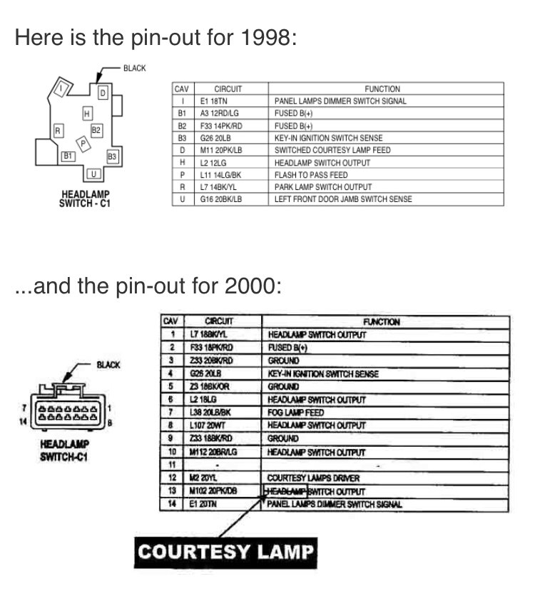
Generic, third-party wiring diagrams found in cheap repair manuals often contain errors or lack the detail required for modern BCM-integrated systems. For the most accurate data, owners should consult the official guide provided by Mopar. These Factory Service Manuals (FSM) provide the exact pinouts and connector views needed for precise diagnostics. For community-driven insights and real-world troubleshooting shared by fellow enthusiasts, visiting a specialized expert tips forum can be invaluable. If a repair seems beyond your current skill level, especially regarding TIPM internal failure, checking Ram specs for local repair costs can help you decide when to see a professional technician with dealer-level diagnostic tools.
By The Numbers
Nighttime Accident Rate
Max Halogen Lifespan
Max Ground Resistance
Understanding the shift from analog relays to digital PWM control is essential for modern Dodge Ram electrical work. Using a multimeter in conjunction with a precise wiring diagram is the most trusted method for identifying circuit failures before they lead to more costly module replacements. Safety precautions, such as disconnecting the battery and using quality connectors, prevent long-term damage to the vehicle’s computer systems. Before starting your repair or upgrade, ensure you have the correct year-specific diagram and high-quality diagnostic tools to maintain the professional standards of your Dodge Ram’s electrical system. A well-executed repair doesn’t just fix a light; it ensures the continued safety and reliability of your truck for thousands of miles to come.
Frequently Asked Questions
Where can I find a wiring diagram for my specific year and model of Dodge Ram?
The most reliable source for a specific Dodge Ram headlight wiring diagram is a Factory Service Manual (FSM). Professional-grade databases like Alldata or Mitchell 1 provide exact schematics used by technicians. Alternatively, reputable online forums often host scanned versions of these diagrams for various generations (1500, 2500, and 3500 models).
What do the different wire colors in the headlight circuit represent?
While colors vary by year, Dodge typically uses a color-over-stripe convention. For example, a White/Light Green wire might represent the left low beam, while a White/Tan wire represents the right. Solid Black is almost universally the ground. Always cross-reference your specific VIN with a professional schematic to confirm, as trim levels can alter these assignments.
How do I test the headlight circuit with a multimeter?
To test the circuit, set your multimeter to DC Volts. With the headlights switched on, probe the power pin of the harness connector; it should read approximately 12.6V to 14V. Next, switch to Ohms to check the ground pin for continuity to the chassis. High resistance or low voltage indicates a corroded connection or a failing TIPM module.
What are the common causes of headlight problems in Dodge Rams?
Common issues include blown fuses, oxidized connectors, and failing TIPM (Totally Integrated Power Module) units. On 2006+ models, the computer may shut down a circuit if it detects an improper load, often caused by installing incorrect LED bulbs without resistors. Physical damage to the wiring harness near the front fenders is also a frequent culprit in older trucks.
Can I upgrade my Dodge Ram headlights to LEDs or HIDs?
Yes, but it requires a professional approach. Because newer Rams use Pulse Width Modulation (PWM), you must use ‘CANbus-ready’ bulbs or install a load resistor/anti-flicker harness. This prevents the truck’s computer from thinking a bulb is out and cutting power to the circuit. Always ensure your upgrade follows the factory wiring logic to maintain reliability.


![2023 Ram 1500 Classic Tradesman: Full Specs & Data [2026]](https://truckguider.com/wp-content/uploads/2026/03/2023-ram-1500-classic-tradesman-featured.webp)