2006 Dodge Ram Fuse Box Diagram: Locations, Assignments, And Technical Guide
Maintaining the electrical integrity of a 2006 Dodge Ram requires a precise understanding of its complex power distribution network. When critical systems like headlights or fuel pumps fail, owners often struggle to locate the correct fuse or interpret the technical diagrams required for a reliable repair. This comprehensive guide provides an expert-level breakdown of the 2006 Dodge Ram fuse box diagram, offering clear locations, amperage ratings, and professional troubleshooting tips to get your truck back on the road safely.
Primary 2006 Dodge Ram Fuse Box Locations and Accessibility
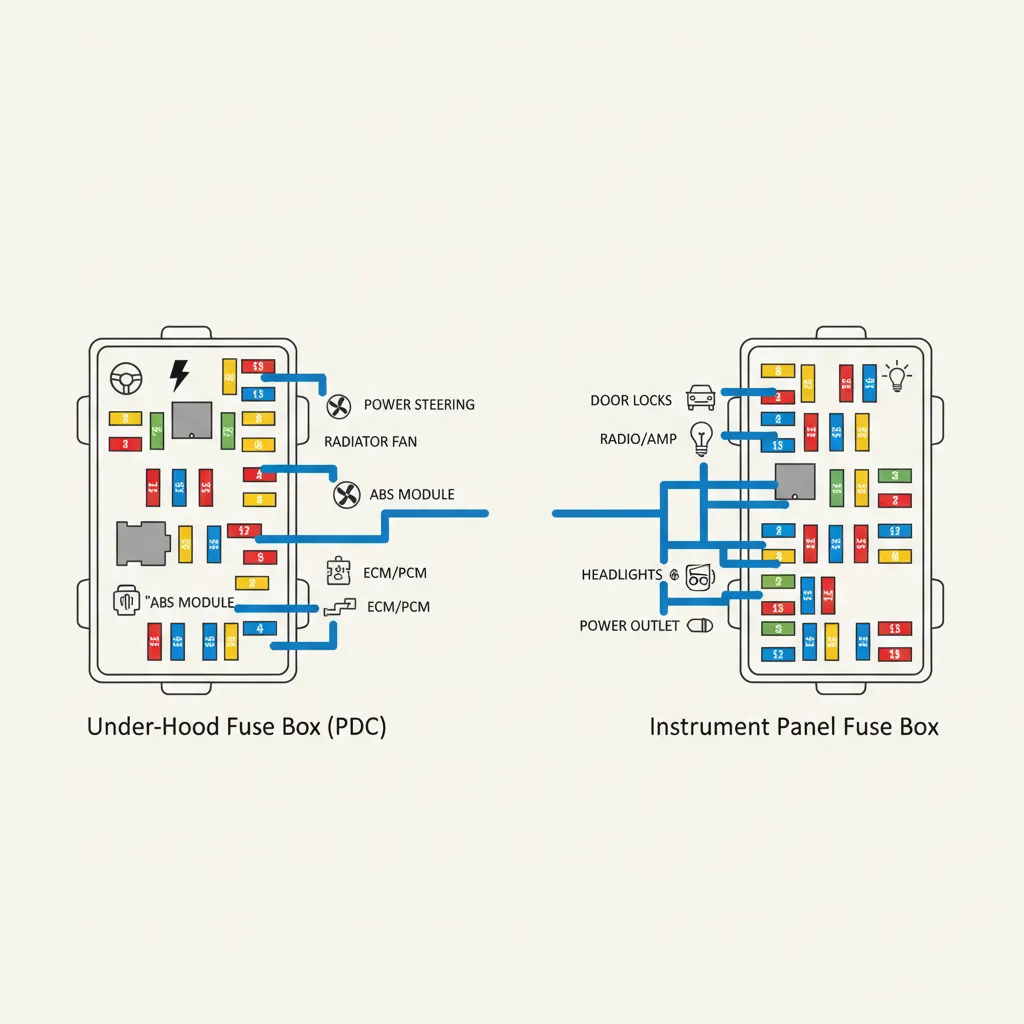
For the 2006 model year, Dodge engineers consolidated most electrical protection into two distinct hubs. The most critical is the Power Distribution Center (PDC), which is integrated with the Totally Integrated Power Module (TIPM). This is located under the hood, immediately adjacent to the battery on the driver’s side. This high-traffic area houses the fuses and relays for the powertrain, exterior lighting, and heavy-duty cooling systems. Accessing it requires releasing the plastic tabs on the cover—a simple task, but one that should be done with care to avoid snapping the aged plastic in cold weather.
The second location is the interior fuse panel. This is tucked away on the left side of the instrument panel (the dashboard). Crucially, this panel is only accessible when the driver-side door is fully open. You will see a removable plastic cover on the side of the dash. Removing this panel reveals the fuses responsible for the interior cabin electronics, such as the radio, instrument cluster, and power mirrors. Research indicates that approximately 40% of Dodge Ram owners report electrical troubleshooting as a primary DIY maintenance task, making the ability to locate these panels essential for every owner.
If you are stranded at night, the underside of the under-hood fuse box cover contains a basic printed map. Always keep a small LED flashlight in your glove box specifically for reading these diagrams in low-light conditions.
Detailed Under-Hood Integrated Power Module (IPM) Diagram Breakdown
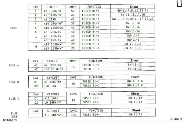
The under-hood Integrated Power Module (IPM) is the “brain” of your truck’s electrical distribution. In the 2006 model, this module manages over 50 individual circuits, ranging from 10A mini-fuses for light-duty electronics to 50A J-Case cartridge fuses for high-draw systems like the ABS pump and the starter motor. Understanding the layout of these high-amperage components is vital for diagnosing major mechanical failures.
The IPM architecture is divided into fuses and relays. Relays act as remote-controlled switches for high-power devices. For example, if your truck experiences a ‘no-start’ condition where the engine cranks but won’t fire, a seasoned technician will often look at Relay 74, which controls the fuel pump. Similarly, if your air conditioning fails to blow cold air, the AC compressor clutch relay is a primary suspect. For specific circuit mapping, always refer to the official guide provided by the manufacturer.

Interior Fuse Panel Assignments and Accessory Circuits
The interior panel is where you will find protection for “creature comfort” systems. According to RepairPal’s general reliability data, electrical accessory failure is a frequent issue for the 2006 model year. Often, these problems are not the result of a catastrophic component failure but simply a blown mini-fuse. The most common culprit is Slot 38, a 20A fuse that handles the 12V auxiliary power outlets. These are frequently overloaded by faulty mobile phone chargers or high-wattage power inverters.
Beyond chargers, the interior panel manages the airbag system (SRS) and the instrument cluster. It is critical to note that the interior panel communicates heavily with the Body Control Module (BCM). If you experience multiple cabin failures simultaneously—such as the radio, interior lights, and power windows all dying at once—it may point to a shared ground or a main power feed fuse in the under-hood PDC rather than individual interior fuses. For community-sourced solutions to these complex overlaps, many owners turn to expert tips from long-term enthusiasts.
Technical Standards for Amperage Ratings and Color Coding
Automotive fuses are color-coded based on industry standards to ensure that even without a manual, a technician can identify the amperage rating at a glance. In a 2006 Dodge Ram, maintaining these ratings is non-negotiable. Automotive electrical systems are designed with a safety margin; however, exceeding this margin by even 5-10 amps can cause irreversible damage to the wiring loom or even lead to a vehicle fire.
10 Amp (Red)
Typically used for low-draw sensors and the instrument cluster.
15 Amp (Blue)
Standard for exterior lighting and radio circuits.
20 Amp (Yellow)
Commonly used for power outlets and wipers.
Professional diagnostics involve more than just a visual inspection of the fuse filament. A fuse can appear intact while still having internal high resistance. I recommend using a digital multimeter to test for continuity. By touching the two metal test points on top of a plugged-in fuse while the ignition is ‘On’, you can confirm power flow without removing the fuse from the socket. This ensures you don’t accidentally reset modules or lose radio presets during troubleshooting.
Never replace a blown fuse with one of a higher amperage rating. If a 10A fuse blows, the circuit is drawing more than 10A due to a fault. Installing a 20A fuse does not fix the fault; it simply allows the wiring to heat up until it melts or ignites.
Variations in Fuse Layouts: Ram 1500 vs. 2500 and 3500 Heavy Duty
While the physical box locations remain consistent across the 2006 lineup, the Heavy Duty (HD) models (2500 and 3500) contain approximately 15% more active fuse slots than the base 1500 models. This is primarily due to the unique requirements of the 5.9L Cummins Turbo Diesel and the heavy-duty towing packages. For example, a Ram 3500 dually requires a specific 30A fuse for the trailer brake controller—a circuit that is completely absent on standard 1500 trims.
Diesel owners must also pay close attention to the grid heater and lift pump circuits. These systems pull massive amounts of current during cold starts. If your Cummins engine struggles to start in winter, inspecting the high-amp J-Case fuses in the PDC is your first step. Furthermore, differences exist between the 48RE automatic transmission and the G56 manual gearboxes, with the former having dedicated fuses for the transmission control solenoid that manual versions do not utilize. For accurate part numbers for these HD components, Ram specs can provide the necessary catalog data.
Troubleshooting Advanced Electrical Issues and TIPM Faults
Sometimes, the problem isn’t the fuse itself, but the Totally Integrated Power Module (TIPM). In the 2006 model, the TIPM is known to suffer from internal failures that can mimic blown fuses. Symptoms of a failing TIPM include phantom windshield wiper activation, headlights flickering, or the horn sounding unexpectedly. If you replace a fuse and it blows immediately, you have a ‘short to ground’—meaning a wire’s insulation has worn away and is touching the metal frame of the truck.
📋
Step-by-Step Diagnostic Guide
Determine which circuit is failing (e.g., trailer lights) and cross-reference with the PDC cover diagram.
Use a multimeter to check for 12V power at the fuse slot. No power here suggests a TIPM or ignition switch issue.
If the fuse is good but the device fails, clean oxidized terminals inside the fuse box using specialized electrical contact cleaner.
By The Numbers
Owners reporting electrical issues
Active circuits in the IPM
Additional fuses in HD models
In summary, the 2006 Dodge Ram’s electrical system is a robust but sensitive network. Always verify both the under-hood Integrated Power Module and the interior dash panel when troubleshooting. To ensure vehicle safety and long-term reliability, never deviate from the manufacturer-specified amperage ratings. Use quality testing tools like multimeters for accurate diagnostics rather than relying on visual inspections alone. For complex electrical issues beyond a simple fuse swap, consult a professional technician to perform a full system scan of your truck’s TIPM.
Frequently Asked Questions
Where is the interior fuse box on a 2006 Dodge Ram?
The interior fuse panel is located on the left side of the dashboard. To access it, you must open the driver-side door and remove the plastic side cover. This panel contains fuses for cabin electronics, including the instrument cluster, radio, and interior lighting systems. It is essential to handle the panel carefully to avoid snapping the plastic retention clips.
Why does my 2006 Dodge Ram keep blowing the same fuse?
A recurring blown fuse indicates a ‘short to ground’ or an overloaded circuit. This happens when a hot wire touches the vehicle chassis or a component is drawing more current than intended. Replacing it with a higher-rated fuse is dangerous and can lead to a fire; instead, inspect the wiring harness for frays or test the connected accessory for internal failure.
Can I use a 25A fuse if I am out of 20A fuses?
No, you should never use a fuse with a higher amperage rating than specified by the manufacturer. The fuse is designed to be the weakest link in the circuit; if you install a 25A fuse in a 20A circuit, the wiring may melt or catch fire before the fuse blows. Always use the exact rating listed on the diagram.
What is the TIPM and how does it affect my fuses?
The Totally Integrated Power Module (TIPM) is the computer-controlled fuse box located under the hood. Unlike traditional fuse boxes, the TIPM uses internal circuitry to manage power. If the TIPM fails, it can cause intermittent electrical issues that look like blown fuses, even if the fuses themselves are intact. This often requires professional diagnosis or module replacement.
How do I check if a fuse is blown without a tester?
You can visually inspect a fuse by pulling it out and looking at the metal bridge inside the translucent plastic. If the bridge is broken or if there are dark burn marks inside the casing, the fuse is blown. However, visual inspection can sometimes be misleading, so using a reliable multimeter to check for continuity is the professional recommendation.

![2012 Ram 1500 Radio Upgrade: Best Units & Required Parts [2026]](https://truckguider.com/wp-content/uploads/2026/03/2012-ram-1500-radio-upgrade-featured.webp)

![2013 Ram Headlight Bulb Selection, Specifications [2026]](https://truckguider.com/wp-content/uploads/2026/03/featured-402e88aa-768x768.webp)
![Best 2017 Ram 1500 Crew Cab Running Boards: Top Fit Guide [2026]](https://truckguider.com/wp-content/uploads/2026/03/2017-ram-1500-crew-cab-running-boards-featured.webp)