2006 Honda Ridgeline Fuse Box Diagram: 2026 Repair Guide

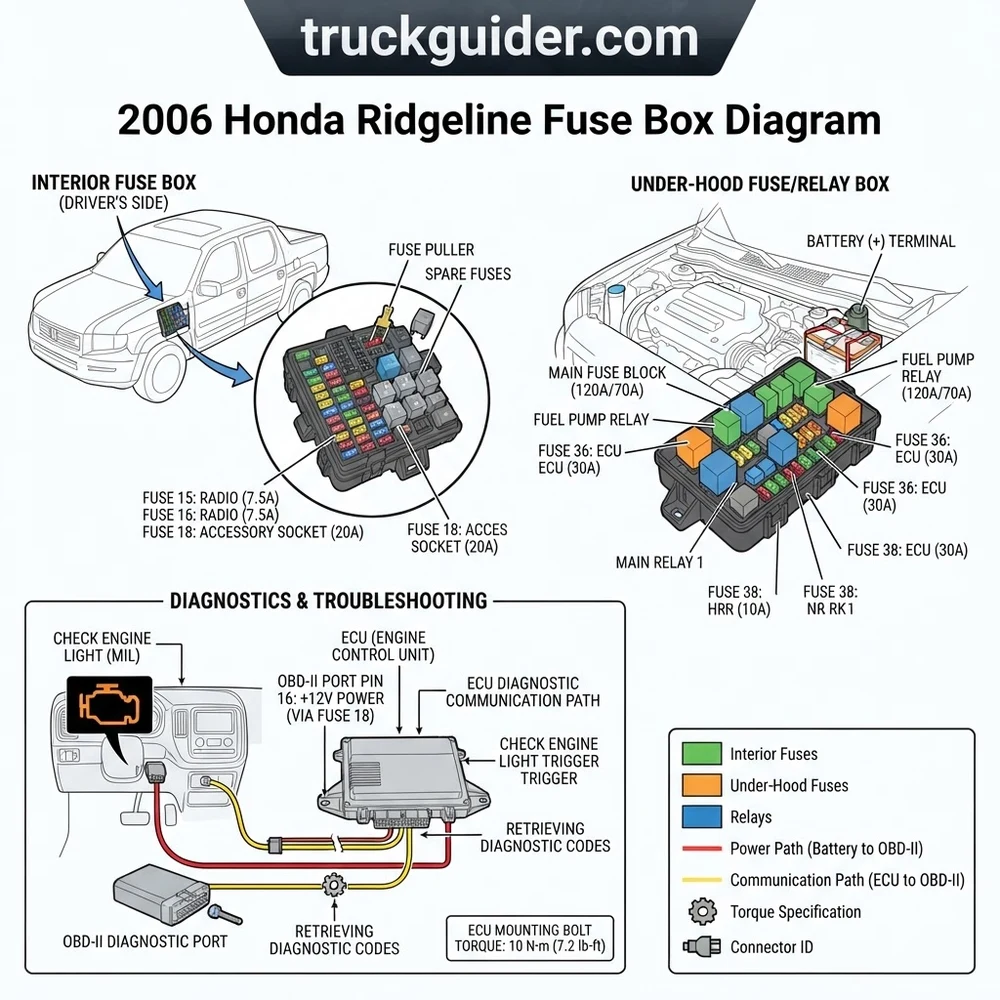
The 2006 Honda Ridgeline features two primary fuse blocks: the main under-hood box positioned adjacent to the battery housing high-amp fuses and ECU relays, and the secondary under-dash box situated beside the driver kick panel. The interior unit protects cabin circuits, instrument clusters, and the OBD-II diagnostic port.
📌 Key Takeaways
- Primary under-hood block contains multi-fuses rated up to 120A for main battery power and alternator feeds.
- Interior fuse panel rests on the lower driver-side kick panel and powers the OBD-II port via fuse #5 (7.5A).
- Main battery cable terminal clamps require a torque spec of 4.0 Nm (35 in-lb) to prevent intermittent relay chatter.
- Water intrusion through the driver-side cowl seam often causes corrosion on internal kick-panel fuse terminals.
- Always isolate the 12V battery ground before servicing high-amperage bolt-down block fuses or ECU main circuits.
The first-generation 2006 Honda Ridgeline, powered by the 3.5-liter J35A7 V6 powertrain, relies on a distributed electrical architecture to govern everything from the variable torque management all-wheel-drive system (VTM-4) to basic cabin telemetry. When diagnosing electrical faults, having an accurate 2006 honda ridgeline fuse box diagram is vital for tracing open circuits, isolating parasitic battery drains, and testing component feed voltages. This heavy-duty unibody pickup separates its circuit protection into four distinct hardware junction centers. Understanding the location, fuse ratings, circuit duties, and associated diagnostic codes for each panel allows professional technicians and experienced owners to bypass guesswork and resolve electrical issues with precision.
2006 Honda Ridgeline Fuse Box Diagram and Component Locations


Honda engineered the 2006 Ridgeline with electrical distribution nodes positioned strategically near the subsystems they protect. Rather than channeling all high-amperage lines into a single junction box, the platform utilizes an under-dash interior panel, two under-hood junction enclosures, and a battery-mounted high-current multi-fuse block. Knowing the exact physical location of each panel prevents unnecessary disassembly of cabin trim or engine compartment shrouds.



Under-Dash Interior Driver Compartment Junction Box


The primary interior fuse panel is mounted in the driver-side footwell, positioned on the lower left kick panel just forward of the hood release latch and parking brake pedal assembly. To access this panel, remove the lower plastic access cover by releasing the retaining pawls with a panel popper or a flat-blade tool. This junction block houses the micro-relays and mini blade fuses for driver-operated amenities, instrument cluster feeds, the body control unit, and safety control systems. Additionally, the cabin harness interfaces directly with the Ridgeline ignition switch wiring schematic through the back of this integrated junction assembly.
Primary Under-Hood Relay and Fuse Panel
The main engine compartment fuse box is situated on the passenger side of the engine bay, directly behind the windshield washer reservoir neck and adjacent to the engine coolant reservoir. Encased in a water-resistant, high-impact thermoplastic housing, it features a dual-latch lid with an embossed 2006 honda ridgeline fuse box diagram on its underside. This hub delivers battery-positive (+B) power directly to major powertrain systems, the programmed fuel injection (PGM-FI) sub-harnesses, cooling fans, and high-load heating elements.
Secondary Under-Hood Auxiliary Fuse Block
Located on the driver side of the engine compartment, mounted between the air cleaner housing and the master cylinder/brake booster assembly, sits the auxiliary under-hood fuse block. This smaller rectangular housing contains protection circuits dedicated primarily to the Vehicle Stability Assist (VSA) modulator pump, auxiliary lighting, trailer towing package harness sub-relays, and optional power accessory circuits. Releasing the single retaining clip on the forward-facing edge allows the cover to pivot upward for rapid terminal inspection.
Battery Terminal High-Current Fuse Block


Mounted directly to the positive battery post is an integrated multi-fuse link block. This specialized block acts as the initial layer of circuit protection directly downstream of the 12-volt battery. It incorporates discrete fusible links molded within a transparent inspection window, shielding the alternator charging feed, primary ignition switches, and downstream fuse boxes from severe catastrophic direct-to-ground short circuits.


Disconnect the negative battery cable before servicing or loosening the battery terminal multi-fuse block. Bridging the main 100A/70A fusible link bus bar to chassis ground with a metal hand tool will cause instantaneous arcing, harness thermal damage, and potential battery rupture.
2006 Honda Ridgeline Fuse Box Diagram Tables: Dash and Engine Bay


The following assignment tables detail the fuse positions, nominal amperage ratings, protected circuits, and operating power sources across the 2006 Honda Ridgeline power distribution network. The circuits utilize standard automotive mini blade fuses (ATM) in lower-current branches and high-amp maxi fuses or cartridge fuses (J-Case) for high-draw electro-mechanical components.
Under-Dash Interior Fuse Assignment Table
This interior junction block controls switched and unswitched low-voltage electronics. Power types designate circuits supplied continuously via battery positive (+B), circuits active only with the ignition switch in Accessory (ACC), and circuits energized in the RUN or START positions (IG1/IG2).
| Slot # | Amperage | Fuse Type | Protected Circuit / Load Description | Power Type |
|---|---|---|---|---|
| 1 | 15A | Mini Blade | Drive-by-Wire (DBW) Throttle Actuator Relay, Fuel Pump Relay | IG1 (Run/Start) |
| 2 | 15A | Mini Blade | SRS Airbag Control Unit, Occupant Position Detection System | IG1 (Run/Start) |
| 3 | 10A | Mini Blade | Daytime Running Lights (DRL) Module, Meter Assembly | IG1 (Run/Start) |
| 4 | 15A | Mini Blade | Power Window Master Switch, Sunroof Control Module | IG1 (Run/Start) |
| 5 | 10A | Mini Blade | OBD-II Data Link Connector (Pin 16), Backup Lights, VTM-4 ECU | +B (Constant) |
| 6 | 7.5A | Mini Blade | ABS/VSA Modulator Control Unit, Steering Angle Sensor | IG1 (Run/Start) |
| 7 | 30A | Mini Blade | Front Windshield Wiper Motor, Washer Fluid Pump | IG1 (Run/Start) |
| 8 | 10A | Mini Blade | ECU / PCM Power Logic, Alternator Voltage Regulator Sense | IG1 (Run/Start) |
| 9 | 15A | Mini Blade | Front 12V Accessory Power Outlet Circuit (Center Console) | ACC (Switched) |
| 10 | 7.5A | Mini Blade | Instrument Panel Illumination, Climate Control Head Illumination | +B (Constant) |
| 29 | 15A | Mini Blade | Rear Cabin 12V Accessory Power Outlet Circuit | ACC (Switched) |
| 32 | 20A | Mini Blade | Driver Power Seat Adjustment Motors | +B (Constant) |
Primary Under-Hood Fuse Box Assignment Table
The under-hood distribution block handles raw alternator generation feeds, transient spikes from inductive electromagnetic coils, and high-current fan loads necessary for maintaining proper engine operating temperature and refrigerant system pressures.


| Position | Amperage | Fuse Type | Protected Circuit / Load Function | Power Feed |
|---|---|---|---|---|
| 1 | 20A | Mini Blade | Condenser Fan Motor (A/C Sub-Cooling Assembly) | +B (Constant) |
| 2 | 15A | Mini Blade | Honda A/C Compressor Clutch Relay, Field Coil Magnetic Engage | +B (Constant) |
| 3 | 30A | J-Case Cartridge | Main Engine Radiator Cooling Fan Motor | +B (Constant) |
| 4 | 15A | Mini Blade | Ignition Coils 1 through 6, Spark Control Circuits | IG1 (Run/Start) |
| 5 | 15A | Mini Blade | Automatic Transmission Solenoid Assembly, Shift Lock Solenoid | IG1 (Run/Start) |
| 6 | 30A | J-Case Cartridge | VSA Modulator Solenoids and Hydraulic Stability Valves | +B (Constant) |
| 7 | 40A | J-Case Cartridge | Cabin Heater Blower Motor Speed Controller | +B (Constant) |
| 8 | 20A | Mini Blade | VTM-4 Rear Differential Actuator Solenoids | +B (Constant) |
| 9 | 10A | Mini Blade | PCM Engine Control Module / ECU Memory Backup, Hazard Warning | +B (Constant) |
| 10 | 20A | Mini Blade | Front Fog Light Relay Bus and Filaments | +B (Constant) |
Battery Terminal Fuse Block Specifications
The battery post multi-fuse block bridges high-amp current straight into the harness. Individual elements cannot be replaced by standard mini fuses; a blown element requires replacing the complete terminal assembly or multi-fuse module (OEM Part Number: 38231-SDA-A01).
| Block Segment | Rating | Hardware Fastener | Direct Subsystem Protected |
|---|---|---|---|
| Pole A (Main) | 100A | M6 Bolt (10mm Head) | Alternator B-Terminal Battery Charge Output Cable |
| Pole B (Cabin) | 70A | M5 Screw (8mm Head) | Under-Dash Interior Junction Box Main Supply Feed |
Factory torque spec for the positive battery post multi-fuse M6 mounting bolts is 9.8 N·m (7.2 lb-ft / 87 lb-in). The battery post clamp pinch nut requires a torque spec of 5.0 N·m (44 lb-in). Do not overtighten, or the plastic resin foundation will deform and cause intermittent ground faults.
Blown Fuse Symptoms: Accessory Outlets, Check Engine Light, and ECU


When an automotive blade fuse interrupts current to an active automotive circuit, the symptoms can range from an unpowered cabin accessory to a catastrophic no-crank/no-start condition accompanied by multi-system trouble lights. Correlating physical failure symptoms with the 2006 honda ridgeline fuse box diagram narrows the diagnostic path without requiring random component swapping.
Loss of 12V Accessory Power Outlet Circuit and Audio Power


The most common failure on the 2006 Ridgeline involves the center console 12V accessory power outlet circuit. Overloading this circuit with high-wattage power inverters or tire inflators blows Under-Dash Fuse 9 (15A) or Fuse 29 (15A). If both the cigarette lighter socket and the console power port go dark simultaneously, verify whether the radio head unit also lost power. The radio shares switched ACC rail signals with Fuse 9. Replacing the fuse with an identical mini blade fuse restores power, but repeated blowing indicates foreign debris inside the socket shorting the spring-loaded center contact pin directly to the outer barrel ground.
ECU Communication Loss and Engine Stall Triggers
If the PCM/ECU loses unswitched battery memory power (+B) via Under-Hood Fuse 9 (10A) or key-on ignition power through Under-Dash Fuse 8 (10A), the engine will immediately cut out or crank continuously without firing. A key diagnostic symptom of a blown ECU power fuse is an unresponsive check engine light (CEL/MIL); typically, the bulb illuminates for a 2-second bulb check when cycling the key to ON. If the light remains unlit and your scan tool displays an error such as “Unable to Establish Link” or “Communication Error,” check Under-Dash Fuse 8 and Under-Hood Fuse 9 before suspecting a failed powertrain control module.


VTM-4 System and Oil Pressure Switch Electrical Drops
The Ridgeline’s Variable Torque Management 4-wheel drive system is electronically coupled to the powertrain controller. If Under-Hood Fuse 8 (20A) blows, the instrument panel will illuminate the amber “VTM-4” lamp. In many instances, this happens alongside a check engine light storing a diagnostic code such as P2646 or P2647 (VTEC Oil Pressure Switch Circuit Malfunction). While mechanics often rush to replace the spool valve, a transient ground short or corroded harness dropping power to the PCM engine management sub-fuse can mimic low engine oil pressure faults by destabilizing reference voltages to the sensor circuit.
Coolant Fan Failure and Coolant Flow Disruption
When Under-Hood Fuse 3 (30A) or Under-Hood Fuse 1 (20A) burns out, the dual electric cooling fan motors will not engage. This directly compromises thermal exchange across the radiator core, stagnating dynamic coolant flow during idle and low-speed driving. The dashboard engine coolant temperature gauge will quickly climb toward the red zone when the vehicle is stationary, but begin dropping back to normal operating temperature once highway speeds are achieved. This pattern distinguishes electrical fan failure from mechanical thermostat binding or water pump impeller detachment.
A notorious failure point on the 2006 Ridgeline is the Honda A/C compressor clutch relay (Omron/Mitsuba designator in the primary under-hood box). When internal relay contacts fuse together under heavy inductive loads, continuous current feeds the compressor clutch field coil, draining the battery flat overnight while the vehicle sits parked with the engine off.
Testing Fuses with a Multimeter and Diagnosing OBD-II Electrical Codes


Pulling every individual mini blade fuse to perform a visual check is inefficient and runs the risk of reseating terminals into worn, loose female receptacles. The most reliable diagnostic method utilizes a digital multimeter (DMM) to evaluate voltage drops and circuit integrity across the test tabs while the fuse stays seated in its socket.
- Prepare the Electrical System: Connect your DMM’s black negative lead directly to a solid, unpainted chassis ground or the negative battery terminal clamp. Turn the Ridgeline ignition switch to the ON (II) position to energize the switched ignition buses without cranking the starter motor.
- Perform Live In-Slot Voltage Testing: Set the DMM to DC Volts (20V scale). Every standard mini blade fuse exposes two small bare metal test points on its exposed outer face. Place the sharp red meter probe against the first exposed test pad, note the voltage (normal is ~12.4 to 12.6V), and then touch the red probe to the second test pad on the same fuse.
- Both sides show 12V+: The circuit is intact and receiving input voltage.
- One side shows 12V+, other side shows 0.0V: The internal fuse filament is blown open.
- Both sides show 0.0V: The circuit is unswitched or not energized by the current ignition key switch state (e.g., fog light circuit with switch turned OFF).
- Perform an Unpowered Continuity Check: If bench-testing a pulled fuse or testing with the battery disconnected, switch the DMM to the Ohms/Continuity setting (symbolized by a diode or audio wave). Place probes across both blades. A functional fuse reads 0.0 to 0.2 Ohms (with an audible beep); a blown fuse indicates an open circuit, showing “OL” or infinite resistance.
- Extract Using the Fuse Puller Tool: Avoid needle-nose pliers, which crush the plastic casing of mini blade fuses and fracture the retention socket terminals. Utilize the OEM white plastic fuse puller tool snapped into its retention bracket inside the primary under-hood relay box lid. Slide the slotted ends squarely down the fuse body, pinch firmly, and extract vertically.
- Diagnose OBD-II Data Link Connector (DLC) Dead Faults: If connecting an OBD-II diagnostic tool yields no power (screen remains dead), investigate Under-Dash Fuse 5 (10A). Pin 16 of the diagnostic data connector receives unswitched 12V power through this fuse line. Ground integrity can be checked at Pin 4 (chassis ground) and Pin 5 (signal ground) using your multimeter’s resistance function.
- Differentiate Electrical DTCs from Mechanical Failures: When resolving powertrain diagnostic trouble codes, check fuse integrity before condemning mechanical assemblies. A blown sensor heater fuse creates immediate open-loop DTCs like P0135 or P0141 (O2 Sensor Heater Circuit). In contrast, codes like P0341 (Phase Camshaft Correlation) generally indicate mechanical Honda Ridgeline J35A7 timing belt replacement guide alignment issues or timing chain/belt stretch rather than blown circuit protection, as the sensor harness relies on shared sensor reference rails directly from the ECU.
2006 Honda Ridgeline Fuse Box Diagram Troubleshooting FAQ
Which fuse powers the OBD-II diagnostic port on a 2006 Ridgeline?


The OBD-II Data Link Connector (DLC) receives continuous 12-volt battery power at Pin 16 via Under-Dash Fuse 5 (rated at 10A). If an OBD-II code scanner fails to power up when plugged in, this fuse is usually open. Also verify Under-Hood Backup Fuse 9 (10A), which maintains power to the PCM keep-alive memory bus and secondary diagnostic circuits.
What causes the Honda A/C compressor clutch relay to fail repeatedly?
The factory-installed Mitsuba and Omron A/C compressor clutch relays in the main under-hood box are vulnerable to internal contact pitting and inductive flyback voltage spikes from the compressor’s field coil. When the internal contacts weld closed, the clutch stays engaged continuously, blowing Under-Hood Fuse 2 (15A) or draining the battery overnight. Honda released updated, heavy-duty relay revisions (OEM Part Number: 39794-SDA-A05) to eliminate this issue.
Can a blown fuse mimic mechanical timing chain or VTEC pressure problems?
Yes. If the power supply line feeding the VTEC solenoid and oil pressure switch experiences high resistance or an intermittent fuse connection at Under-Dash Fuse 1, the engine computer registers sudden drops in sensor reference voltage. This triggers diagnostic code P2646 or P2647 (Rocker Arm Actuator System Performance), which is often misdiagnosed as sludged engine oil, low mechanical oil pressure, or jumped valve timing.
What is the torque spec for the battery terminal fuse block bolts?
According to factory workshop specifications, the M6 bolts securing the high-amperage cables and the 100A/70A multi-fuse link to the battery post terminal block require a torque spec of 9.8 N·m (7.2 lb-ft / 87 lb-in). The terminal pinch bolt clamp requires 5.0 N·m (44 lb-in). Exceeding these torque specs will crack the phenolic fuse carrier, while undertightening introduces high electrical resistance and charging voltage drops.
How do I identify a blown battery terminal multi-fuse block without removing it?
The high-current multi-fuse block features clear poly-carbonate observation windows on the outer housing. Shine a bright inspection light through the window to visually inspect the internal serpentine zinc fusible links. If the link is severed, melted, or blackened, the fuse element has blown. You can also measure the voltage drop across the input battery post lug and the downstream M6 terminal; any reading greater than 0.1V under load confirms excessive internal resistance or an open circuit.
Step-by-Step Guide to Understanding the 2006 Honda Ridgeline Fuse Box Diagram
Identify – Determine the failing circuit and cross-reference your accessory failure against the layout legend on the cover.
Locate – Access the under-hood block beside the intake air box or the interior panel beneath the left kick dash panel.
Reference – Match the coordinate numbers on the 2006 honda ridgeline fuse box diagram to pinpoint the exact fuse position.
Test – Inspect the fuse element visually or probe both exposed metal test tabs using a 12V test light or multimeter.
Verify – Insert an exact replacement amp-rated fuse, secure the cover, and ensure normal circuit operation without immediate blowout.
Troubleshoot – If a check engine light persists, connect an OBD-II scanner to extract any active diagnostic code and inspect ECU wiring.