How to Flush Heater Core: The Ultimate Guide (Ford, Chevy, Ram) 2026
The automotive heater core, a compact liquid-to-air heat exchanger, represents a critical node in the modern vehicle’s thermal management system. While often regarded merely as a comfort feature for cabin climate control, the heater core plays a vital safety role in defrosting and defogging windshields, ensuring visibility in adverse weather conditions.
Furthermore, in light-duty trucks and SUVs—specifically platforms like the Ford F-Series, Chevrolet Silverado/Tahoe, and Ram 1500—the heater core serves as a parallel cooling circuit that contributes to the overall heat rejection capacity of the engine.
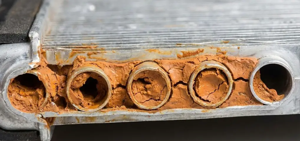
Despite its importance, the heater core is frequently the first component to suffer from cooling system neglect. Its physical location, often the highest point in the cooling loop relative to the engine block, makes it a natural trap for entrained air. Its internal structure, consisting of narrow aluminum or copper tubes (often 3-5mm in diameter) designed to maximize surface area, transforms it into a low-velocity settling zone for particulate matter, precipitated solids, and polymerized coolant sludge.
This report provides an exhaustive, expert-level analysis of the heater core flushing process. It moves beyond superficial “how-to” instructions to explore the thermofluid dynamics of fouling, the chemical interactions of flushing agents with aluminum substrates, and vehicle-specific protocols for major domestic truck platforms.
By synthesizing data from technical service bulletins (TSBs), chemical safety data sheets (SDS), and professional service procedures, this document establishes a definitive standard for restoring heat transfer efficiency in fouled automotive heat exchangers.
The Economics of Repair vs. Restoration
The decision to flush a heater core rather than replace it is driven primarily by labor economics. In modern vehicle architecture, the heater core is typically housed within the HVAC plenum box, deeply embedded behind the dashboard firewall.
- Replacement Complexity: Accessing the core often requires the removal of the steering column, instrument cluster, center console, and the entire dashboard assembly.
- Cost Differential:
- Professional Replacement: Industry labor guides (Mitchell1) estimate replacement times between 6.0 and 10.0 labor hours for vehicles like the 2015+ Ford F-150 or 2014+ Chevy Silverado. At current labor rates ($150-$200/hr), plus parts, the total cost frequently exceeds $1,500 to $2,500.
- Professional Flush: In contrast, a chemical back-flush is a service that typically requires 1.0 to 2.0 labor hours, costing between $150 and $300.
- DIY Potential: For the vehicle owner, a DIY flush can be performed for under $50 in materials (chemicals, hoses, adapters), representing a potential savings of over 95% compared to professional replacement.
How to Flush Your Heater Core
Restore your vehicle’s cabin heat, prevent engine overheating, and save over $800 in repair costs. A data-driven guide to the “Backflush” technique.
Success Rate
85%
of cases resolved without replacement
The Cost of Cold Air
A clogged heater core restricts hot coolant from entering the cabin’s ventilation system. While a professional mechanic often recommends a full replacement—a labor-intensive job requiring dashboard removal—a DIY flush is remarkably cheap.
The chart compares the average cost of materials for a DIY flush versus the national average for a professional heater core replacement.
Cost Analysis: DIY vs. Shop
Massive Savings
You can save roughly $850 by attempting a flush first. Even if it fails, the low initial investment makes it a mandatory first step.
Time Investment
Flush: 1-2 Hours.
Replacement:
6-10 Hours (Dashboard Removal).
What Clogs the Core?
The heater core acts like a filter for your cooling system. Because its passages are narrower than the main radiator, debris settles here first. Understanding the composition of the clog helps in choosing the right chemical flush.
- ⚠️ Rust & Scale: Common in older iron blocks or when water is used instead of distilled coolant.
- ⚠️ Silicate Drop-out: Old antifreeze breaks down into a gel-like goo (alumina).
- ⚠️ Electrolysis: Electrical currents in the fluid causing rapid aluminum corrosion.
Primary Causes of Clogging
Data aggregated from automotive repair analysis reports (2024)
The “Backflush” Technique
Sending water in the opposite direction of normal flow is the secret. It dislodges debris wedged against the inlet tubes.
Cool Down
Wait until the engine is completely cold. Opening a hot system causes severe burns.
Locate & Disconnect
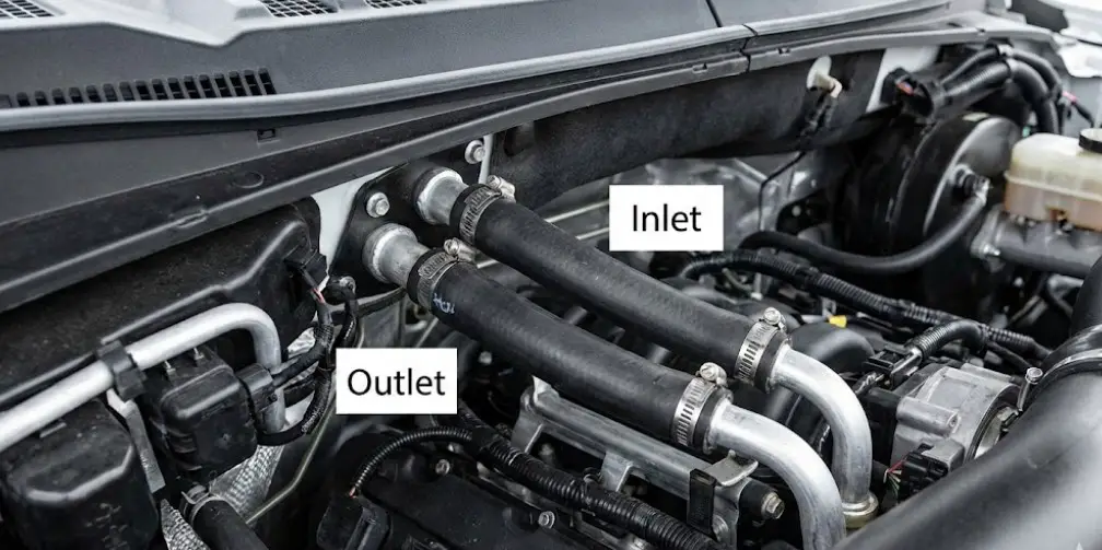
Find the two heater hoses at the firewall. Disconnect them from the engine side.
Reverse Flush
Connect garden hose to the Outlet hose. Push water IN the exit to push junk OUT the inlet.
Chemical Soak
If water fails, pour radiator flush cleaner into hoses. Let sit for 15 mins, then flush again.
Thermodynamic Restoration
This chart illustrates the vent temperature ramp-up time of a vehicle before and after a successful flush. The goal is to reach operating temperature (approx 140°F/60°C at the vent) quickly.
Did it work?
- ✅ Sweet smell of coolant is gone (if leak fixed).
- ✅ Both heater hoses are hot to the touch.
- ✅ Vent air is uncomfortable to hold hand against.
Tool Checklist
© 2026 TruckGuider Infographics
Thermodynamics and Failure Modes: Why Heater Cores Fail
To understand how to flush a heater core, one must first understand the mechanisms of heat transfer and the specific pathologies that inhibit it.
The Physics of Heat Transfer Efficiency
The heater core operates on the principle of convective heat transfer. Hot engine coolant (190°F - 220°F / 88°C - 104°C) flows through the tubes, heating the tube walls. Heat is conducted to the attached fins, and forced air from the blower motor convects this heat into the cabin.
The efficiency of this system is governed by the overall heat transfer coefficient ($U$). Fouling degrades $U$ through two primary mechanisms:
- Thermal Resistance ($R_f$): A layer of sludge, rust, or silicate gel coats the interior walls of the tubes. This material acts as an insulator, preventing thermal energy from conducting from the fluid to the aluminum metal. Even a thin film of 0.1mm can significantly reduce heat output.
- Flow Restriction ($\Delta P$): As deposits accumulate, the cross-sectional area of the tubes decreases. While the continuity equation ($A_1V_1 = A_2V_2$) suggests fluid velocity increases through a constriction, in a complex hydraulic network like an engine, the fluid follows the path of least resistance. Severe clogging increases the pressure drop across the core, causing the water pump to bypass the heater circuit entirely in favor of the radiator or bypass hose. This results in a massive reduction in mass flow rate ($\dot{m}$), starving the core of fresh thermal energy.
Chemical Failure Modes
Silicate Dropout (IAT/HOAT Coolants)
Traditional Inorganic Additive Technology (IAT) coolants (green) and some Hybrid OATs (gold) use silicates to passivate aluminum surfaces. Silicates form a microscopic protective layer that inhibits corrosion. However, silicates are unstable. If the coolant is not changed every 2 years, the silicates "drop out" of solution, precipitating as a greenish-grey abrasive gel. This gel accumulates in the low-flow areas of the heater core, polymerizing into a clay-like substance that blocks flow.
The Dex-Cool Sludge Phenomenon (OAT Coolants)
General Motors' Dex-Cool (Orange) utilizes Organic Acid Technology (2-Ethylhexanoic Acid) for extended service life (5 years/150,000 miles). While effective at preventing corrosion, 2-EHA has a known vulnerability:
- Air Sensitivity: When exposed to air (due to low coolant levels or leaks), Dex-Cool can react to form a thick, rust-colored iron oxide sludge.
- Incompatibility: Mixing OAT (Orange) with IAT (Green) coolants triggers a chemical reaction that precipitates solid sludge almost immediately. This is a common cause of total heater core blockage in GM trucks.
Electrolysis and Galvanic Corrosion
Electrolysis occurs when the coolant becomes an electrolyte due to improper electrical grounding of the engine or chassis. Stray voltage (>0.3V) passes through the coolant, causing rapid anodic dissolution of the aluminum heater core. The byproduct is aluminum oxide—a white, fluffy powder that packs tightly into the tubes. This is a "terminal" failure mode; flushing may remove the powder, but the core walls are often thinned to the point of pinhole leaks.
Diagnostic Protocols: Distinguishing Clogs from Mechanical Failure
A common diagnostic error is assuming "no heat" indicates a clogged core. In modern trucks, mechanical failures in the HVAC distribution box are equally common.
The Inlet/Outlet Temperature Differential Test
The definitive test for a flow restriction is measuring the temperature delta ($\Delta T$) across the heater core hoses at the firewall.
Procedure:
- Warm the engine to operating temperature (thermostat open).
- Set HVAC to Max Heat and Full Blower.
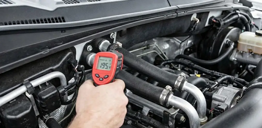
- Measure the temperature of the two heater hoses entering the firewall using an infrared thermometer or contact probe.
Interpretation Logic:
| Inlet Temp | Outlet Temp | Diagnosis | Action |
| Hot (~200°F) | Hot (~190°F) | Good Flow. Problem is likely Blend Door Actuator. | Inspect Blend Door. |
| Hot (~200°F) | Cold/Lukewarm | Restricted Flow. Coolant is moving too slow or not at all. | Flush Heater Core. |
| Cold | Cold | No Flow. Air lock, bad water pump, or closed thermostat. | Check Coolant Level/Pump. |
Visual and Olfactory Diagnostics: The Leak Check
Before flushing, one must rule out a breach in the core. Flushing a leaking core will remove the rust scale temporarily sealing the leak, resulting in a catastrophic flood of hot coolant into the cabin.
- The "Fog" Test: A greasy, fog-like film on the interior windshield that smears when wiped is a hallmark of glycol vaporization. This film is distinct from normal humidity fog—it is sticky and sweet-smelling.
- The Olfactory Sign: A distinct, sweet, maple-syrup odor inside the cabin confirms coolant escapement.
- Coolant Loss: If the reservoir requires frequent topping off but no puddles appear under the truck, the leak is likely into the HVAC box or passenger footwell.
- Warning: If these signs are present, DO NOT FLUSH. Replacement is the only option.
The "Blend Door" False Positive
In vehicles like the Chevy Silverado and Ram 1500, the blend door actuator (an electric motor that moves a flap to mix hot and cold air) frequently fails.
- Symptoms: A clicking noise from behind the dashboard indicates stripped plastic gears in the actuator.
- Differentiation: If the hose inlet/outlet temps are both hot, but the vent air is cold, the heater core is working, but the air is not being directed through it. Do not flush; replace the actuator.
Chemical Analysis: Selecting the Right Flushing Agent
The choice of chemical agent is a critical engineering decision that balances cleaning efficacy against material safety. Aluminum, the primary material of modern heater cores, is amphoteric—meaning it corrodes in both highly acidic and highly alkaline environments.
4.1 Comparative Analysis of Common Flushing Agents
| Agent | Active Ingredient | Target Deposit | Aluminum Safety Profile | Recommended Use |
| White Vinegar | Acetic Acid (CH₃COOH) | Mineral Scale (Calcium Carbonate) | Low | DIY "Hack". Effective but risky. Must be diluted 50/50 and limited to <2 hours soak time. |
| CLR | Lactic & Gluconic Acid | Hard Water Scale, Rust | Very Low | Not Recommended. Label explicitly states "Do Not Use on Aluminum." High risk of etching. Only use for <15 mins as last resort. |
| BlueDevil Flush | Sodium Citrate + EDTA | Grime, Light Rust, Oil | High | Safe for extended run times. Uses chelation (EDTA) rather than acid attack. |
| Irontite Thoro-Flush | Sodium Metasilicate | Heavy Scale, Rust, Sludge | Moderate | Professional grade. Highly effective but requires PPE. Do not leave in system indefinitely. |
| Motorcraft VC-1 | Proprietary Acid Blend | Iron Oxide (Rust) | High | OEM Recommended for Ford iron-block engines (Triton/EcoBoost). Specifically formulated for Ford cooling systems. |
| Evapo-Rust | Selective Chelating Agents | Rust (Iron Oxide) | High | Excellent for rust removal. Non-toxic, non-corrosive to base metals. Can be left in for days. |
The Vinegar Controversy
Vinegar is a popular DIY recommendation, but its use on aluminum requires caution.
- Mechanism: Acetic acid dissolves calcium deposits (scale).
- Risk: It also attacks the aluminum oxide protective layer. If left too long or used undiluted, it can thin the tube walls, leading to failure weeks or months later.
- Protocol: If using vinegar, restrict the soak time to 1-3 hours maximum and neutralize thoroughly with copious water flushing.
Safety Data Sheet (SDS) Insights
- Irontite Thoro-Flush: The SDS indicates this product causes "severe skin burns and eye damage" (Category 1). It is a strong alkaline cleaner. Users must wear chemical-resistant gloves and eye protection.
- BlueDevil: While safer, the SDS still warns of skin irritation. It relies on Citrate (a safe buffer) and EDTA (a metal chelator) to lift deposits into suspension without dissolving the base metal.
Tooling and Setup: Professional vs. DIY Approaches
Proper tooling is the differentiator between a messy, ineffective attempt and a successful repair.
5.1 Fluid Containment and Safety
- Containment: The flush process will generate 5-10 gallons of hazardous waste (water mixed with ethylene glycol and lead/aluminum precipitates). This must be captured in large buckets and disposed of at a recycling center; it is illegal and unethical to dump it in storm drains.
- PPE: Safety glasses are mandatory. Pressurized air and water can blow chemical sludge back into the operator's face.
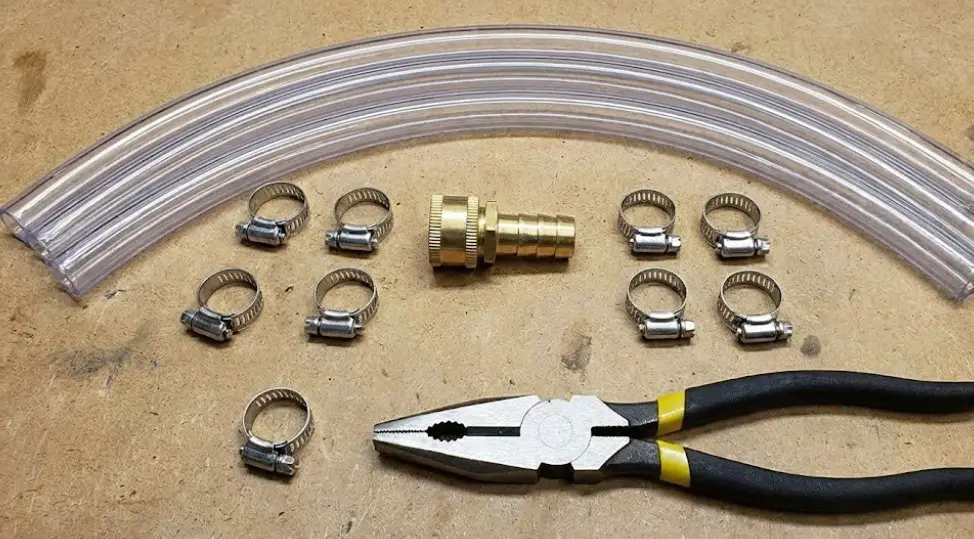
Hose Connections and Adapters
To flush the core, one must adapt the vehicle's heater core nipples (typically 5/8" or 3/4" barb) to a garden hose (GHT).
- DIY Adapter: A cheap and effective solution involves purchasing:
- 2x lengths (4 ft each) of 5/8" or 3/4" Clear Vinyl Tubing.
- 1x "Garden Hose Female to 5/8 Barb" fitting.
- Hose clamps.
- Professional Tools:
- Thexton 815 Flush Gun: A specialized tool that connects to a garden hose and an air line, allowing the operator to pulse air into the water stream with a trigger. This "water hammer" effect is highly effective at dislodging solid debris.
- Lisle 39400 Angled Disconnect Tool: Essential for Ford trucks (2004+) and some GMs. These vehicles use "quick connect" fittings instead of hose clamps. Attempting to remove them with pliers often breaks the heater core nipple or the plastic fitting.
Vehicle-Specific Hose Diameters
| Vehicle | Hose Size (Inlet/Outlet) | Connection Style | Notes |
| Ford F-150 (2009-2014) | 5/8" & 3/4" (Hybrid) | Quick Connect | Requires white clip disconnect tool. |
| Chevy Silverado (1999-2006) | 5/8" & 3/4" | Quick Connect (Plastic) | Plastic fittings are brittle. Upgrade to metal recommended. |
| Dodge Ram (Gen 3/4) | 5/8" | Spring Clamps | Accessible, usually clamped directly to metal pipes. |
| Jeep Grand Cherokee | 5/8" | Spring Clamps | Passenger side blend door failure mimics clog. |
Comprehensive Step-by-Step Flushing Protocols
This section details the operational procedure for a complete restoration flush, incorporating "Back-Flushing," "Chemical Soaking," and "Air Shocking."
Phase 1: Preparation and Access
- Cool Down: Ensure the engine is cold. Opening a pressurized cooling system at operating temperature is dangerous.
- Locate Hoses: Identify the two heater hoses passing through the firewall.
- Tip: In Silverados, they are on the passenger side firewall. In F-150s, they may be tucked behind the battery or engine cover.
- Disconnect:
- Clamped Hoses: Use pliers to slide the spring clamp back. Twist the hose with "hose pliers" to break the seal before pulling. Do not yank, as this can crack the heater core nipple.
- Quick Connects (Ford/GM): Insert the disconnect tool into the coupling to depress the locking tabs. Push the hose in slightly, then pull out.
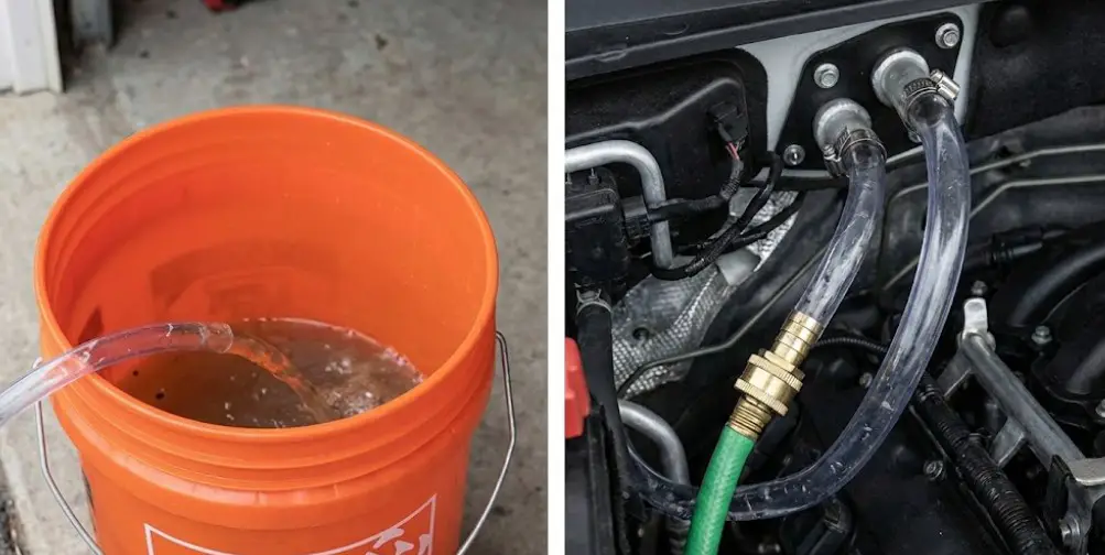
- Extension Hoses: Attach the clear vinyl tubing to both heater core nipples. Secure with clamps to prevent blow-off during pressurization. Route the "Outlet" tube into a 5-gallon bucket.
Phase 2: The Hydro-Dynamic Back-Flush
Objective: Reverse the flow of fluid to dislodge debris wedged in the inlet screen.
- Connect Water: Attach the garden hose adapter to the Outlet nipple of the heater core (reversing the normal flow direction).
- Initial Flush: Turn on the water. Start with low pressure. Observe the clear discharge tube. You will likely see coolant followed by brown/cloudy water.
- Check Flow: If water flows freely, proceed. If flow is trickling or blocked, stop—high pressure could rupture the core. Move to Chemical Soak.
- Cycle Direction: Once clear, switch the water source to the Inlet nipple (forward flush). Run for 1 minute.
- Repeat: Cycle back and forth 3-4 times. The mechanical agitation of reversing flow is crucial for dislodging silicate gel.
Phase 3: The Chemical Reactant Soak
Objective: Dissolve mineral scale and sludge that water cannot remove.
- Purge Water: Use low-pressure compressed air (or lung power) to blow the water out of the core.
- Fill with Agent: Pour the selected chemical (e.g., BlueDevil, diluted Vinegar, or CLR) into the inlet tube until it flows out the outlet.
- Elevate: Tie the clear tubes up to the hood latch or secure them high up so the chemical stays inside the core.
- Soak Time:
- CLR: 10-15 minutes MAX.
- Vinegar: 1-2 hours.
- BlueDevil/Irontite: Follow package instructions (usually 10-30 mins for a static flush).
- Agitation (Optional): Some technicians use a drill-powered fluid pump to circulate the chemical in a closed loop for 30 minutes, keeping the fluid moving and heated (if using hot water).
Phase 4: The Air-Assisted "Shock" Flush
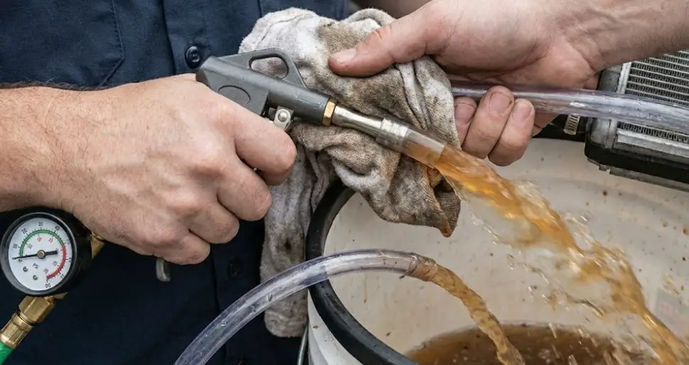
Objective: Use kinetic energy to eject heavy solids (rust flakes, casting sand).
- Rinse: Flush the chemical out with water thoroughly.
- Fill & Blast: Fill the core with water. Insert an air blow gun into the hose. Seal with a rag or tape.
- The "Hammer": deliver short, sharp bursts of air (20-40 PSI). Do not exceed 40 PSI or sustain pressure, as heater cores are thin-walled.
- Observation: This "water hammer" effect expands the water slug rapidly, often ejecting chunks of rust and silicone sealant that steady water flow could not move.
- Final Rinse: Flush with copious amounts of water until the discharge is crystal clear.
Critical Visuals and Plans
Diagram Plan: Reverse Flow Dynamics
Description: A schematic comparing "Normal Flow" vs. "Reverse Flush."
- Normal Flow: Shows coolant entering the inlet, with wedge-shaped debris (scale/rust) getting stuck in the tube openings, tightening like a check valve under pressure.
- Reverse Flush: Shows water entering the outlet. The pressure applies force to the back of the debris wedge, unseating it and allowing it to be flushed out the inlet. This visual explains why simply running water through the inlet rarely works.
Chart Plan: Temperature Recovery Curve
Description: A line graph showing "Vent Temperature" over time.
Post-Flush Restoration: Air Bleeding and Refilling
A successful flush can be undone by improper refilling. The heater core is a high point; leaving air trapped inside results in an "air lock" that stops flow, mimicking a clog.
The Physics of Airlocks
Air is compressible; water is not. If a large air bubble remains in the heater core, it acts as a pneumatic spring. The water pump's pressure compresses the air bubble rather than pushing fluid through the loop. This stops circulation.
Manual Bleeding Techniques (No Tools)
- Jacking the Front: Park the truck on a steep incline or jack up the front end. This makes the radiator cap the highest point in the system, encouraging air to migrate away from the heater core.
- RPM Variation: With the radiator cap off (engine cool) or the expansion tank open, run the engine. Once the thermostat opens, hold the RPM at 2,000-3,000 for 10-second intervals. The increased pump velocity forces fluid through the core, flushing air bubbles out.
The "Spill-Free" Funnel Method (Lisle Funnel)

- Tool: The Lisle Spill-Free Funnel connects to the radiator or degas bottle with a leak-proof adapter.
- Process: Fill the funnel 1/3 full. Run the engine. As air burps out, coolant from the funnel is immediately drawn in to replace it. This prevents new air from entering.
Vacuum Filling (The Gold Standard)
For stubborn systems (like the 5.4L Triton or GM 5.3L), a vacuum airlift tool is recommended.
- Mechanism: The tool uses a venturi to pull a vacuum on the entire cooling system (hoses collapse).
- Benefit: It proves the system is sealed (vacuum hold test) and then sucks fresh coolant into every void, eliminating airlocks instantly. This is the factory fill method.
Advanced Topic: The Ford "Quick Connect" Engineering Challenge
Owners of 2004+ Ford F-150s and Expeditions face a unique challenge with heater hose connections.
- Design: Ford uses a plastic quick-connect coupling with internal O-rings.
- Failure Mode: Over time, the O-rings harden. When disconnected for flushing, they often fail to reseal, causing leaks at the firewall upon reassembly.
- Service Tip: It is highly recommended to apply silicone dielectric grease to the metal heater core nipples before reconnecting the hose. This lubricates the O-ring and helps it swell slightly to create a better seal. If a leak persists, the internal O-rings or the entire hose assembly must be replaced.
Conclusion and Future Outlook
Flushing a heater core is a procedure of high utility that offers a lifeline to aging vehicles suffering from thermal neglect. By understanding the chemistry of the clog—whether it is silicate dropout in an older Ford or Dex-Cool sludge in a Chevy—and selecting the appropriate chemical and mechanical flushing method, vehicle owners can often restore heating performance to factory specifications.
The shift toward aluminum heat exchangers and organic acid coolants has made the system more robust against corrosion but more sensitive to contamination and electrolysis. Future maintenance should prioritize:
- Coolant Quality: Using only distilled water to mix coolant (preventing scale).
- Regular Intervals: Changing coolant every 3-5 years to prevent additive dropout.
- Electrolysis Checks: Regularly testing for stray voltage to prevent the silent destruction of the core.
This guide empowers the technician and the owner to execute this repair with the precision of a thermal engineer, ensuring comfort and safety for the life of the vehicle.
Frequently Asked Questions
Q1: Can I flush a heater core without removing it from the vehicle?
A: Yes. In fact, "flushing" specifically refers to cleaning it while it is installed. Removing the heater core is a major labor operation (6-10 hours) usually reserved for replacement when the core is leaking. Flushing is done by disconnecting the hoses at the firewall.
Q2: Is it safe to use CLR or Vinegar in my aluminum heater core?
A: Use extreme caution. The manufacturer of CLR advises against using it on aluminum. Vinegar is safer but still acidic; it should be diluted 50/50 with water and not left in the system for more than 2-3 hours. Commercial flushes like BlueDevil or Prestone are buffered to be safer for aluminum.
Q3: Why does my heat work when I'm driving but gets cold when I stop at a red light?
A: This is a classic symptom of a partial clog or low coolant level. When driving (higher RPM), the water pump spins faster, creating enough pressure to force some coolant through the restricted core. At idle (low RPM), the pressure drops, and the resistance of the clog stops the flow.
Q4: How do I know if it's my heater core or my blend door actuator?
A: Touch the heater hoses at the firewall. If both hoses are hot, coolant is flowing, and the problem is likely the blend door (mechanical flap) inside the dash. If one hose is hot and the other is cold, the core is clogged.
Q5: Can I use tap water to flush the core?
A: You can use tap water for the flushing process (to push out debris), but the final fill must be done with distilled water and coolant. Leaving tap water in the system introduces minerals (calcium/magnesium) that will cause future clogging and scale.


![2Nd Gen Dodge Ram For Sale [2026]](https://truckguider.com/wp-content/uploads/2026/03/featured-f8e34e32-768x417.webp)