6.7 Cummins Valve Cover Torque Specs & Bolt Sequence Guide 2026
The 6.7L Cummins ISB turbo-diesel engine serves as the heavy-duty backbone for the Ram 2500, 3500, and commercial chassis cab platforms. Maintaining this legendary powerplant requires uncompromising adherence to exact factory fastener specifications.
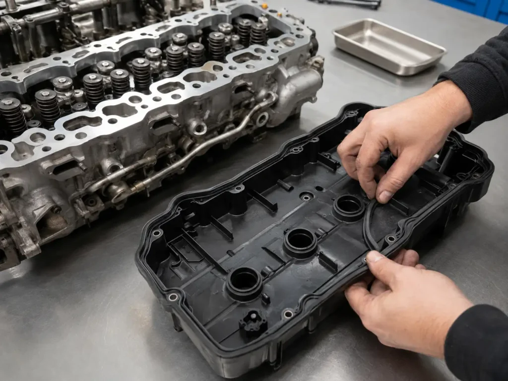
The valve cover assembly acts as the primary barrier against massive top-end oil leaks and crankcase pressurization failures. Routine service procedures on this component demand extreme precision and a thorough understanding of clamping force dynamics.
Improper installation techniques remain the leading cause of cracked composite covers, sheared M8 fasteners, and immediate post-service oil leaks. This exhaustive technical analysis explores the precise torque specifications, mandatory tightening sequences, and interconnected valvetrain procedures for the 6.7L Cummins.
The 6.7L Cummins Torque Manual
A precise technical analysis of valve cover specifications, mandatory sequences, and critical maintenance intervals for the RAM diesel engine.
Precision in Protection
The valve cover assembly on a 6.7L Cummins ISB serves as the primary barrier against massive oil leaks and internal crankcase pressurization.
Maintaining this system requires exact factory fastener specifications to ensure the molded rubber gasket seals properly without cracking the composite cover.
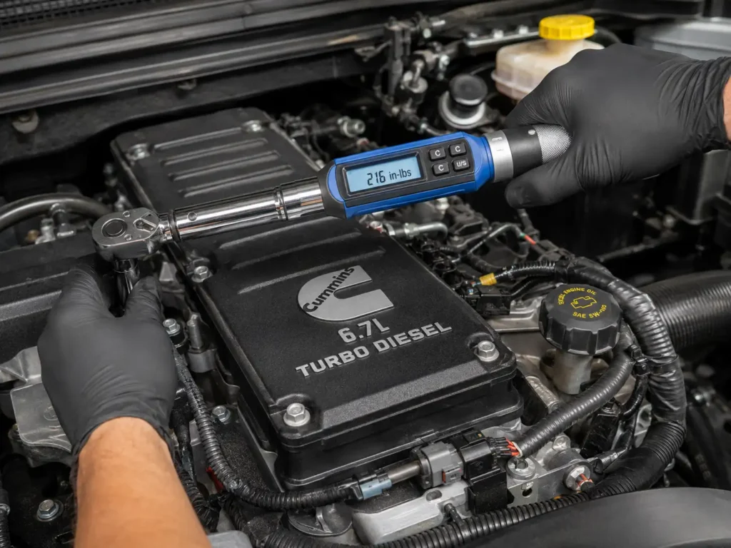
Technicians must use calibrated inch-pound wrenches to avoid the catastrophic errors common with heavy 1/2-inch drive tools at low ranges.
The “Golden” Specification
The factory target of 18 ft-lbs (216 in-lbs) is engineered to compress the gasket without exceeding the elastic limit of the M8 fasteners.
Common errors, such as using wheel lug torque values, lead to instant fastener fracture and expensive cylinder head repairs.
Operating within the “Safe Clamping Zone” ensures long-term thermal stability across thousands of heating and cooling cycles.
Mandatory Tightening Sequence
Applying torque in a random order causes cover warping. Follow this center-out, crisscross pattern to flatten the gasket like a squeegee against a window.
Generational Valvetrain Matrix
While external valve cover specs remained identical, the internal valvetrain transitioned to hydraulic lash adjusters in 2019.
| Component | 2007.5 – 2018 Specs | 2019 – 2026 Specs |
|---|---|---|
| Valve Cover | 18 ft-lbs (216 in-lbs) | 18 ft-lbs (216 in-lbs) |
| Rocker Arm Fasteners | 27 ft-lb | 27 ft-lb (Hydraulic) |
| Injector Hold Down | 89 in-lb | 89 in-lb |
| Connector Tube Nut | 37 ft-lb | 37 ft-lb |
| Injector Harness Nuts | 11 – 13 in-lb | 11 – 13 in-lb |
The CCV Connection
A clogged Crankcase Ventilation (CCV) filter is the primary cause of repeat valve cover leaks.
Blocked filters cause internal pressure to skyrocket, forcing oil past the gasket regardless of how well it was torqued.
Install Dry
Molded rubber gaskets are engineered to be installed perfectly dry. Never use RTV silicone, as it causes uneven clamping and galley contamination.
Cold Engine Only
Metals expand at different rates. Torquing a hot engine yields false readings; as it cools, the clamping force is instantly lost.
Plastic Tools Only
Avoid steel scrapers. Even microscopic gouges in the aluminum cylinder head create permanent capillary leak paths for synthetic oils.
The Definitive 6.7L Cummins Valve Cover Torque Specification
The precise factory torque specification for the 6.7L Cummins valve cover is 18 ft-lbs, which converts perfectly to 216 in-lbs or 24 N·m.
This specific clamping value has remained entirely consistent across all model years from the engine’s 2007.5 debut through the current 2026 production iterations.
Even though Cummins implemented massive valvetrain updates—including the 2019 transition to hydraulic lash adjusters—the external housing and necessary sealing force never changed.
The primary engineered purpose of this specific 18 ft-lb value is to accurately compress the molded rubber gasket. This precise compression seals the internal oil galleys without distorting the lightweight housing.
The Danger of Foot-Pounds Versus Inch-Pounds
A catastrophic error frequently observed in independent repair facilities involves confusing foot-pounds with inch-pounds.
Technicians must utilize a highly calibrated 1/4-inch or 3/8-inch drive inch-pound torque wrench when securing this particular automotive component.
Standard 1/2-inch drive torque wrenches are notoriously inaccurate at the extreme bottom of their mechanical ranges.
Attempting to dial a massive 1/2-inch wrench down to 18 ft-lbs routinely results in accidental over-torquing. This mistake instantly snaps the M8 bolts or fractures the factory composite plastic cover.
By deliberately selecting an inch-pound wrench and setting the dial to exactly 216 in-lbs, the technician guarantees a vastly more precise clamping load.
This meticulous approach ensures perfectly distributed pressure across the entire cast-iron cylinder head and aluminum spacer assembly.
The Mandatory Tightening Sequence
Applying the correct mechanical torque represents only half of the successful sealing equation. The geometric order in which the fasteners are tightened is equally critical to longevity.
Tightening the valve cover bolts in a random, circular, or linear front-to-back sequence will inevitably cause the cover to warp and pinch the rubber gasket.
Engineers strictly mandate a specific “crisscross” or “spiral-out” pattern to distribute the heavy clamping load evenly across the engine block.
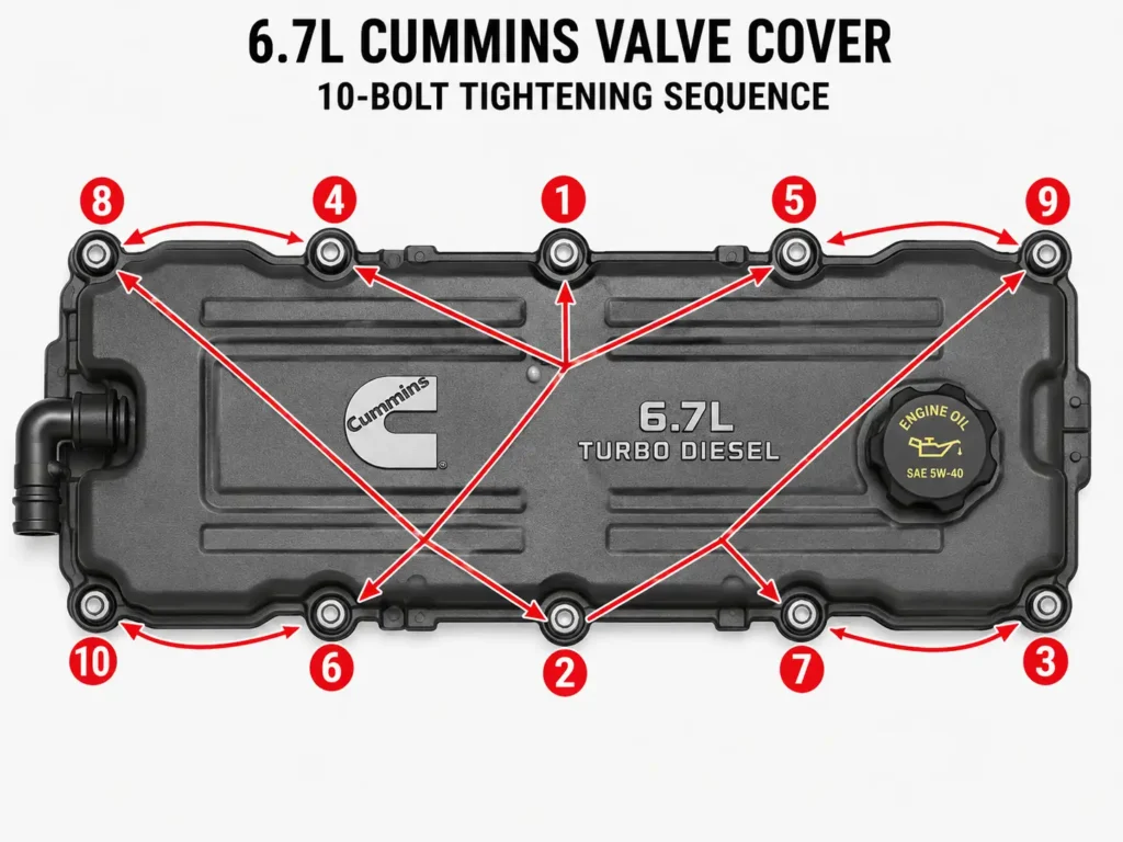
The installation procedure must always initiate at the absolute geometric center of the valve cover assembly. From the center, the technician must progressively alternate outward toward the front fan and rear firewall.
This calculated center-out methodology acts exactly like a squeegee against a window. It pushes the molded rubber gasket flat against the machined cylinder head and absolutely prevents the material from bunching at the extreme corners.
Comprehensive Valvetrain and Top-End Torque Data
Removing the valve cover generally serves as a prerequisite for much deeper top-end engine maintenance. These procedures often include fuel injector replacements, connector tube seating, or complex valve lash adjustments.
The following data sets consolidate the absolute baseline torque specifications for the 6.7L Cummins valvetrain across different generational platforms.
It is vital to note that aftermarket hardware, such as performance head studs, will strictly dictate the use of the manufacturer’s proprietary assembly lubricant and unique torque values rather than these factory specifications.
2007.5 – 2018 Top-End Specifications
| Valvetrain Component | Initial / Preliminary Torque | Final Torque Specification |
| Valve Cover / Rocker Housing | N/A | 212 – 216 in-lb (18 ft-lb) |
| Rocker Arm Assembly Fasteners | N/A | 27 ft-lb |
| Injector Hold Down Bolts | 44 in-lb (To seat injector) | 89 in-lb |
| Injector Connector Tube Nut | 133 in-lb (To seat tube) | 37 ft-lb |
| Injector Harness Wire Nuts | N/A | 11 – 13 in-lb (Extremely fragile) |
| Cylinder Head Bolts (Stock) | 66 ft-lb (Then recheck at 66) | Rotate an additional 90 degrees |
Data metrics sourced from standard factory service references for early and mid-generation 6.7L truck platforms.
2019 – 2026 Top-End Specifications
| Valvetrain Component | Torque Specification | Engineering Notes |
| Valve Cover / Rocker Housing | 212 – 216 in-lb (24 N·m) | Consistent with early generation models |
| Rocker Arm Assembly Fasteners | 27 ft-lb | Applies to newer hydraulic lifter setups |
| Injector Hold Down Bolts | 44 in-lb, then 89 in-lb final | Always verify against aftermarket injector brands |
| Injector Connector Tube Nut | 11 ft-lb, then 37 ft-lb final | Secures the high-pressure fuel union |
| HPFP Gear Mounting Nut | 77 ft-lb (105 N·m) | CP3 / CP4 high-pressure pump specific |
| Acoustic Engine Cover Bolts | 89 in-lb | Secures the top aesthetic NVH cover |
Data metrics sourced from late-model heavy-duty platform service specifications.
The Extreme Impact of Temperature on Fastener Torque
A paramount rule of professional diesel engine maintenance dictates that technicians must only torque valve cover bolts on a completely stone-cold engine.
Modern heavy-duty diesel engines feature massive cast-iron engine blocks mated directly to aluminum or composite top-end components. These dense materials retain severe operational heat for many hours after shutdown.
Cast iron, aerospace aluminum, composite plastics, and molded rubber all feature drastically different coefficients of thermal expansion.
Attempting to apply torque to fasteners while the cylinder head remains hot will result in highly inaccurate torque wrench readings.
Furthermore, as the engine bay naturally cools and the dissimilar metals contract, a hot-torqued bolt will rapidly lose its dynamic clamping force. This thermal contraction immediately compromises the integrity of the fresh gasket seal.
Thread damage is also significantly more likely when threading cold steel bolts into hot, thermally softened aluminum cast heads.
Step-by-Step Valve Cover Gasket Replacement Procedure
Replacing the valve cover gasket on a Cummins ISB 6.7L requires meticulous attention to the surrounding sub-systems.
Top-end leaks typically manifest as fresh oil weeping along the lower flange, pooling near the rear firewall, or generating a heavy burning odor after intense highway towing operations.
Phase 1: Safe Preparation and Teardown
The replacement procedure begins by completely disconnecting the negative battery terminals. This eliminates the massive risk of electrical arcing when working intimately near the highly sensitive injector wiring harnesses.
Next, the technician must remove the plastic aesthetic engine cover. This panel is typically secured by four easily accessible 8mm bolts.
The primary Crankcase Ventilation (CCV) hose must then be carefully detached from the plastic housing and secured out of the immediate workspace.
The integrated injector harness connectors must be manually released with extreme, deliberate caution.
These plastic electrical connectors become exceptionally brittle after surviving thousands of miles of intense under-hood heat cycling.
Rough handling can easily shatter the tiny locking tabs, turning a simple mechanical gasket job into a highly complex, expensive electrical repair.
Phase 2: Systematic Fastener Removal and Deep Inspection
The technician must slowly loosen the external valve cover bolts in stages. Utilizing a reverse-crisscross pattern helps slowly relieve the mechanical tension on the composite plastic or aluminum housing.
Once all peripheral fasteners are entirely free, the cover should be lifted perfectly straight upward.
If the assembly is adhered to the head, prying aggressively against the soft aluminum cylinder head is strictly prohibited. Scratching the delicate mating surface with a steel prybar guarantees a permanent, unfixable leak path.
The hardened old gasket must be fully extracted from the housing. The cover itself must then be rigorously inspected for hairline structural cracks, warped flanges, or heavily crushed bolt bosses.
If the plastic cover exhibits any measurable loss of structural flatness across its plane, installing a new rubber gasket will prove utterly futile. The entire cover assembly must be replaced in this scenario.
Phase 3: Meticulous Surface Preparation
Cleaning the engine’s sealing surface is arguably the most critical technical step of the entire operation.
The technician must exclusively utilize a plastic automotive scraper and non-chlorinated brake cleaner alongside premium lint-free cloths.
The new molded rubber gasket should be pressed firmly and evenly into the machined valve cover groove. Industry best practices mandate that this specific molded gasket be installed completely dry.
Applying heavy beads of RTV silicone is a remarkably detrimental mistake in this specific application.
Silicone creates highly uneven clamping loads across the flange. Worse, it risks squeezing excess silicone beads directly into the internal engine oil galleys, which can catastrophically starve the entire engine of vital lubrication.
Phase 4: Final Seating and Precision Torquing
The valve cover is lowered perfectly straight down onto the exposed cylinder head to prevent rolling or dragging the dry rubber gasket out of its seated groove.
Special attention must always be paid to the extreme rear firewall edge. This area is notoriously difficult to visually align due to severe cab space constraints.
Every single fastener must be threaded into the block by hand for several turns. This completely eliminates the severe risk of cross-threading the soft aluminum cylinder head.
Finally, utilizing the calibrated inch-pound torque wrench, the technician implements the center-out crisscross sequence. All fasteners are brought to the final, verified target of 216 in-lbs (18 ft-lbs).
The Intricate Link Between the CCV Filter and Repeat Oil Leaks
A frequently misunderstood phenomenon within the 6.7L Cummins ecosystem is the direct mechanical correlation between a clogged Crankcase Ventilation (CCV) filter and repeat valve cover gasket blowouts.
For a complete breakdown of how this system impacts overall engine health, automotive professionals frequently consult detailed guides available through SPELAB Auto Parts.
The heavy-duty CCV system actively routes harmful blow-by gases generated inside the engine crankcase back into the intake tract.
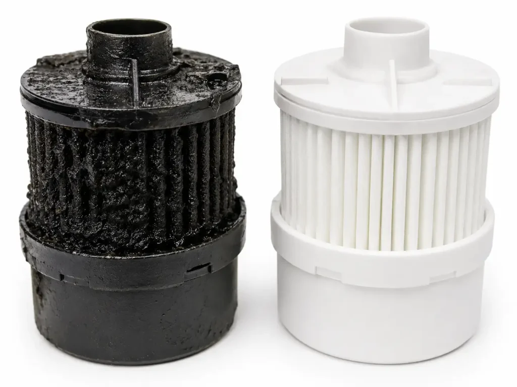
It utilizes a highly specialized, dense filter element to physically separate suspended oil mist from the turbulent air.
On 2007.5 through 2018 model-year trucks, this specific filter requires a complete replacement every 67,500 miles. The 2019 and newer redesigned models stretch this required service interval to 75,000 miles.
When the CCV filter becomes heavily saturated with dense soot and sludgy oil, it physically blocks the only exit path for crankcase gases.
This absolute blockage causes internal engine atmospheric pressure to skyrocket exponentially under heavy load.
Because the massive internal pressure must escape somewhere, it violently forces engine oil directly past the weakest link in the engine’s external sealing architecture. This link is almost invariably the valve cover gasket.
If a technician blindly installs a brand-new valve cover gasket without addressing an overdue, clogged CCV filter, the new gasket will begin leaking again within a matter of days.
Therefore, actively inspecting or proactively replacing the CCV filter is considered mandatory standard operating procedure whenever the valve cover is removed.
OEM Composite vs. Billet Aluminum Valve Covers
As the highly popular ISB 6.7L platform ages gracefully, many truck owners transition away from the factory composite plastic valve covers.
The industry is seeing a massive shift toward aftermarket cast aluminum or CNC-machined billet aluminum alternatives.
Factory plastic covers are inherently susceptible to severe heat-cycle fatigue over long operational lifespans.
After a decade of violently expanding and contracting against a hot cast-iron block, the plastic invariably warps directly around the bolt holes.
This distortion makes a flat, reliable seal physically impossible regardless of the new gasket’s pristine condition.
Billet aluminum covers are CNC-machined from single, solid blocks of 6061-T6 aerospace-grade aluminum.
These premium components offer unmatched structural rigidity and will never warp under massive, heavy towing temperatures.
However, technicians must intimately understand that upgrading to a billet aluminum cover does not authorize an increase in fastener torque.
The 18 ft-lbs (216 in-lbs) specification remains the absolute, non-negotiable limit for this top-end assembly.
While the thick billet aluminum cover itself can withstand massive crushing force, the delicate aluminum threads inside the engine cylinder head remain the limiting structural factor.
Over-torquing will violently strip the engine head regardless of the premium cover’s material strength.
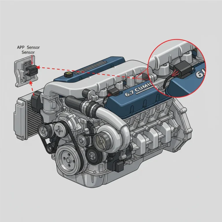
The Injector Harness Pass-Through Dilemma
One of the most delicate mechanical mechanisms integrated into the 6.7L Cummins rocker housing is the fuel injector wiring harness pass-through.
To deliver precise electrical voltage to the common-rail injectors seated deep within the cylinder head, the wiring harness must physically pass directly through the side of the valve cover spacer housing.
The small retaining nuts securing these vital electrical connections demand extreme mechanical empathy from the technician.
The exact factory specification for securing these injector harness nuts is a minuscule, barely noticeable 11 to 13 in-lbs.
Technicians must literally tighten these specific nuts with just two fingers using a dedicated micro nut driver.
Applying a standard heavy ratchet will instantly snap the fragile plastic terminal housings.
This error leads to catastrophic electrical shorts, severe engine misfires, and thousands of dollars in unavoidable replacement costs.
In-Depth Valvetrain Service: The Overhead Set
While safely accessing the internal valve train, technicians frequently perform a complete valve lash adjustment. This procedure is colloquially known in the heavy-duty diesel sector as “running the overhead.”
This routine maintenance is highly recommended every 150,000 miles to restore lost internal engine efficiency and mitigate excessive, damaging valvetrain clatter.
The procedure stringently requires the engine coolant temperature to sit firmly below 140°F (60°C).
This temperature threshold ensures the metallic valvetrain components have fully contracted to their absolute baseline resting states.
Proper Valve Lash Measurements
For the 2007.5 through 2018 solid-lifter 6.7L engines, the strict factory measurement parameters dictate:
- Intake Valve Lash: 0.010 inches (0.254 mm).
- Exhaust Valve Lash: 0.020 to 0.026 inches (0.508 mm to 0.660 mm).
The 2019 and newer engines utilize highly advanced hydraulic lash adjusters across the valvetrain.
This major upgrade means manual overhead sets are largely obsolete on modern trucks unless the valvetrain has been completely rebuilt or specific diagnostic protocols actively demand it.
The Barring Tool and Companion Cylinder Method
Executing the overhead set requires rotating the massive engine crankshaft completely manually.
Technicians utilize a specialized barring tool firmly inserted into the flywheel housing to slowly and deliberately rotate the engine clockwise.
The engine must be brought precisely to Top Dead Center (TDC) on the compression stroke of cylinder number one.
Using the renowned “companion cylinder” method, the technician closely monitors the rocker arms on cylinder number six.
When cylinder six enters crossover—meaning the exhaust valve is closing precisely as the intake valve begins opening—cylinder number one is definitively confirmed at TDC compression.
Once properly positioned, the technician utilizes a calibrated steel feeler gauge to measure the physical gap between the rocker arm socket and the valve crosshead.
The primary lock nut is carefully loosened. The central adjusting screw is then turned until a slight, consistent drag is felt on the feeler gauge.
The lock nut is subsequently locked down permanently to 212 in-lbs (18 ft-lbs) to hold the adjustment.
The engine must then be rotated exactly 360 degrees to place cylinder number six at TDC compression.
This secondary position allows the technician to seamlessly lash the remaining valves in perfect accordance with the Cummins 1-5-3-6-2-4 firing order.
High-Performance Cylinder Head Fasteners
In applications where the 6.7L Cummins has been heavily modified with larger variable geometry turbochargers, enhanced fueling systems, or aggressive tuning calibrations, the factory head bolts are fundamentally inadequate.
Factory torque-to-yield (TTY) head bolts are subjected to a rigorous, permanent-stretch installation sequence.
The technician pulls them to 66 ft-lbs, executes a full recheck at 66 ft-lbs, and then follows with an aggressive 90-degree rotational stretch.
Under extreme internal cylinder pressures routinely exceeding 40-50 PSI of boost, these factory bolts physically stretch beyond their limits.
This elasticity allows the heavy cylinder head to physically lift off the engine block, instantly incinerating the multi-layer steel head gasket.
High-performance engine builds rely exclusively on aftermarket studs manufactured from proprietary aerospace alloys. For detailed charts comparing heavy-duty fasteners, experts reference Pure Diesel Power.
Aftermarket Stud Specifications
When installing premium alloy studs, the factory 66 ft-lb plus 90-degree sequence is entirely discarded and ignored.
Fastener tension is dictated exclusively by the stud manufacturer’s highly specific engineering and metallurgical data.
For standard heavy-duty studs (such as those forged from ARP 2000 material), the final torque goal generally rests at a massive 125 ft-lbs.
This goal is carefully achieved in smooth, incremental steps of 10 to 15 ft-lbs to prevent block distortion.
For extreme Custom Age 625+ alloy studs designed strictly for ultimate competition, the final hot-torque spec routinely reaches an astonishing 150 ft-lbs.
Furthermore, these premium performance fasteners absolutely require aggressive thread lubrication using a proprietary ultra-torque assembly moly-lube.
This specialized lubricant ensures the massive rotational friction does not artificially skew the final clamping load data read by the torque wrench.
Fuel System Sealing and Injector Tube Nuances
A highly critical sub-system directly integrated into the top end of the 6.7L Cummins involves the extreme high-pressure fuel delivery network.
The Bosch common-rail injection system utilizes precision-machined steel connector tubes.
These dense tubes pass completely through the cylinder head casting, intersecting blindly with the side of the seated fuel injectors.
If the torque sequence on these specific components is rushed or executed out of order, catastrophic internal damage occurs.
The hardened connector tube will permanently crush the softer edge of the injector body.
This error results in massive internal fuel leaks that aggressively dilute the engine oil and quickly wash out the primary main bearings.
The Two-Stage Injector Seating Sequence
The factory protocol demands a highly specific, alternating two-stage mechanical procedure to protect the fuel system:
The fuel injector is initially seated deep into the bore, and the two hold-down bolts are preliminarily tightened to a mere 44 in-lbs.
This micro-torque step simply ensures the injector is perfectly plumb, centered, and perpendicular in its bore.
The mechanical pressure is then immediately relieved, leaving the bolts loosely hand-threaded in place.
The high-pressure connector tube is then inserted completely through the side of the cylinder head.
Its retaining nut is pre-torqued to exactly 133 in-lbs (11 ft-lbs).
This specific step securely mates the tapered tip of the tube into the matching tapered receiving port of the fuel injector.
The technician then actively returns to the top hold-down bolts, executing a final alternating torque to 89 in-lbs.
It must be noted that some specific Bosch injector revisions demand 71 in-lbs, requiring the technician to strictly verify the data sheet.
Finally, the external connector tube nut is aggressively torqued to its ultimate specification of 37 to 41 ft-lbs.
This meticulously executed sequence guarantees the high-pressure union—capable of violently containing up to 29,000 PSI of rail pressure—remains absolutely leak-proof.
Diagnosing Persistent Repeat Valve Cover Leaks
When a technician diligently replaces the valve cover gasket, perfectly applies the 216 in-lbs torque, and executes the ideal center-out sequence, success is usually guaranteed.
However, if the vehicle returns to the shop days later with fresh oil actively running down the firewall, a deeper diagnostic matrix must be immediately deployed.
Under-tightening is a highly frequent culprit when amateur technicians rely purely on subjective “hand-feel” rather than calibrated instrumentation.
Heavy-duty diesel engines naturally generate severe, constant high-frequency mechanical vibrations during operation.
Fasteners entirely lacking the precise 18 ft-lbs of structural preload will slowly back out under this intense harmonic resonance.
Once the critical clamp load is lost, the rubber gasket instantly shifts out of its machined groove.
Additionally, if the delicate sealing surface was scraped with sharp carbon-steel razor blades rather than appropriate plastic automotive tools, damage occurs.
Microscopic gouges carved into the soft aluminum will act as highly efficient capillary channels for hot oil.
Modern high-detergent synthetic diesel engine oils are chemically engineered to penetrate the tightest possible mechanical tolerances.
These fluids will rapidly find and ruthlessly exploit these tiny scratches, leading to a permanent weeping leak.
Proper component inspection and the absolute avoidance of harsh metal scrapers are mandatory for long-term sealing success. Engine rebuilders looking for extensive teardown data often consult specifications compiled by Heavy Duty Pros.
Emergency Protocols: Broken Bolts and Stripped Threads
Despite the absolute best intentions, heavy metal fatigue, intense corrosion, or simple human error occasionally disrupts the repair.
This disruption frequently leads to a snapped valve cover bolt or a completely stripped cylinder head thread during reassembly.
Because the required fastening torque is a remarkably low 18 ft-lbs, a bolt that snaps off slightly above the surface is rarely disastrous.
The broken shank can often be backed out effortlessly using standard locking pliers or vice grips.
The binding tension on the steel shank is instantly relieved the exact moment the bolt head shears completely off.
If the bolt unfortunately shears perfectly flush or entirely below the deck surface, a left-handed drill bit paired with a micro-extractor tool is the mandated industry fix.
Stripped internal threads present a vastly more complex metallurgical issue for the technician.
The cylinder head on the 6.7L Cummins is composed of remarkably dense cast iron.
This density makes severe thread pull-out relatively rare unless catastrophic over-torquing occurred with a heavy wrench.
If the M8x1.25 internal threads are indeed completely destroyed, the only permanent, professional-grade repair is the installation of a stainless steel threaded insert.
This specific insert is universally known in the mechanical industry as a Heli-Coil.
Tapping the hole excessively oversize and utilizing a random, non-standard bolt is universally condemned in heavy-duty diesel repair.
This poor practice creates massive parts-matching nightmares for future technicians who service the vehicle.
FAQs
What is the correct valve cover torque for a Ram 6.7L Cummins?
The definitive specification is 18 ft-lbs (which equals 216 in-lbs or 24 N·m) across all 6.7L Cummins platforms from 2007 to 2026. This exact metric ensures the internal rubber gasket achieves optimal compression without physically splitting or distorting the lightweight cover.
Is a specific tightening sequence required during installation?
Yes. Technicians must strictly use a crisscross or spiral-out sequence beginning with the innermost center bolts. They must then alternate outward toward the front fan and rear firewall. This specific geometric strategy prevents the housing from warping and stops the gasket from buckling at the edges.
Do the 2019+ hydraulic lifter engines require entirely different torque specs?
No. Despite the massive internal valvetrain redesign utilizing hydraulic lash adjusters, the top-end specifications remain the same. The external M8 fastening hardware and top-end sealing architecture remain structurally identical, actively demanding the same 18 ft-lbs of clamp load.
Why does my newly installed valve cover gasket continue to leak oil?
The absolute primary cause of immediate, repeat oil leaks is intense crankcase pressurization resulting directly from a clogged CCV filter. If the engine cannot naturally vent blow-by gases, the resulting internal atmospheric pressure will violently push hot oil right past the newly installed gasket.
Can I install a premium Billet Aluminum cover using a much higher torque?
No. While billet aluminum is structurally superior to factory composite plastics, the cast-iron cylinder head threads heavily dictate the maximum mechanical limit. Applying more than 18 ft-lbs severely risks stripping the internal head threads, rendering the entire upgraded cover utterly useless.
What happens if I torque the valve cover while the engine is still hot?
Torquing a hot engine practically guarantees mechanical failure. Aluminum, cast iron, and plastic expand at drastically different thermal rates. Tightening fasteners at operating temperature yields highly false wrench readings; as the assembly eventually cools and contracts, all clamping force is instantly lost.
How tight should the delicate injector harness pass-through nuts be?
The pass-through electrical nuts require an incredibly delicate 11 to 13 in-lbs of torque. Over-tightening with a standard wrench will immediately shatter the plastic housing, leading directly to electrical arcing and severe, damaging engine misfires.
Should I apply heavy RTV silicone to the new rubber gasket?
No. High-quality molded rubber gaskets are explicitly engineered to be installed perfectly dry. Adding thick silicone completely interferes with uniform compression dynamics and poses a severe mechanical risk of internal oil galley contamination if excess material breaks loose.