Dodge Ram 1500 Fuel Pump Connector Diagram And Pinout Specifications
When a Dodge Ram 1500 refuses to start, stalls unexpectedly under load, or exhibits a fluctuating fuel gauge, the source of the failure is often hidden within the complex electrical path of the fuel pump connector. As a seasoned technician, I have seen countless DIYers and even junior mechanics replace an entire fuel pump assembly only to find the vehicle still stranded because of a charred terminal or a corroded ground wire. Diagnosing a fuel delivery issue requires more than just swapping parts; it demands a precise understanding of the wiring diagram and pinout to distinguish between a dead pump motor and a compromised electrical connection. This official guide provides detailed wiring diagrams, pinout specifications across vehicle generations, and expert troubleshooting steps to help you accurately diagnose and repair your Ram 1500 fuel system with professional-level accuracy.
Locating the Fuel Pump Connector on the Dodge Ram 1500
The fuel pump assembly in a Dodge Ram 1500 is situated at the top of the fuel tank, typically mounted mid-frame between the driver-side frame rail and the driveshaft. Accessing the electrical connector is arguably the most labor-intensive part of the diagnostic process. Unlike some SUVs that feature an interior access panel under the rear seat, the Ram 1500 requires external access, which usually involves one of two primary methods.
Access Method A: Dropping the Fuel Tank
Dropping the tank is the standard procedure in most repair shops. However, it presents significant safety challenges. A Dodge Ram 1500 fuel tank can hold between 26 and 33 gallons; since gasoline weighs roughly 6 pounds per gallon, a full tank can weigh between 200 and 250 lbs. I strongly recommend using a dedicated transmission jack or a fuel tank jack if the tank is more than a quarter full. You must disconnect the filler neck hose and the evap lines before lowering the tank enough to reach the electrical pigtail.
Access Method B: Removing or Tilting the Truck Bed
For those working without a lift, removing the truck bed is often the superior method. By unbolting the 6 to 8 bed bolts and disconnecting the tail light harness, you can use a hoist or a few strong assistants to lift the driver side of the bed. This provides clear, top-down visibility of the wiring harness without disturbing the tank straps or fighting gravity. This is particularly useful for 2019 “New Body Style” DT models where the frame packaging is tighter than previous generations.
Always look for the red or grey slide lock on the connector. These safety tabs must be pushed out (unlocked) before the main release tab can be depressed. Forcing the connector without disengaging the slide lock is the leading cause of broken plastic housings.
Dodge Ram 1500 Fuel Pump Wiring Diagram Variations
Understanding the evolution of the Ram 1500’s electrical architecture is vital for accurate pinout identification. Wiring colors and signal types have changed significantly across the three most recent generations.
Third Generation (2002-2008)
In these models, the fuel pump is a relatively straightforward DC motor system. The connector is typically a 4-pin or 5-pin configuration. The Dark Blue/White wire is frequently the primary 12V power feed coming directly from the Fuel Pump Relay located in the Integrated Power Module (IPM). These systems are known for terminal fretting where the high amperage causes the pins to lose their tension over time.
Fourth Generation (2009-2018)
The fourth generation introduced more complex Totally Integrated Power Modules (TIPM). Wiring gauges were increased to 12 AWG or 14 AWG for the 5.7L Hemi applications to handle the higher flow rates required. You will often see a Dark Blue/Orange or Dark Blue/Yellow wire for the fuel pump motor supply. For more specific Ram specs, community databases often highlight how the TIPM internal relays can fail, mimicking a bad connector.
Fifth Generation (2019-Present) DT Models
Modern DT Rams utilize a Fuel Pump Control Module (FPCM). Instead of a simple 12V constant feed, the pump is often controlled via Pulse-Width Modulation (PWM). This allows the ECM to vary the pump speed based on engine demand, reducing electrical load and heat. Testing these requires a digital storage oscilloscope or a multimeter with a duty cycle function to see the actual command signal.
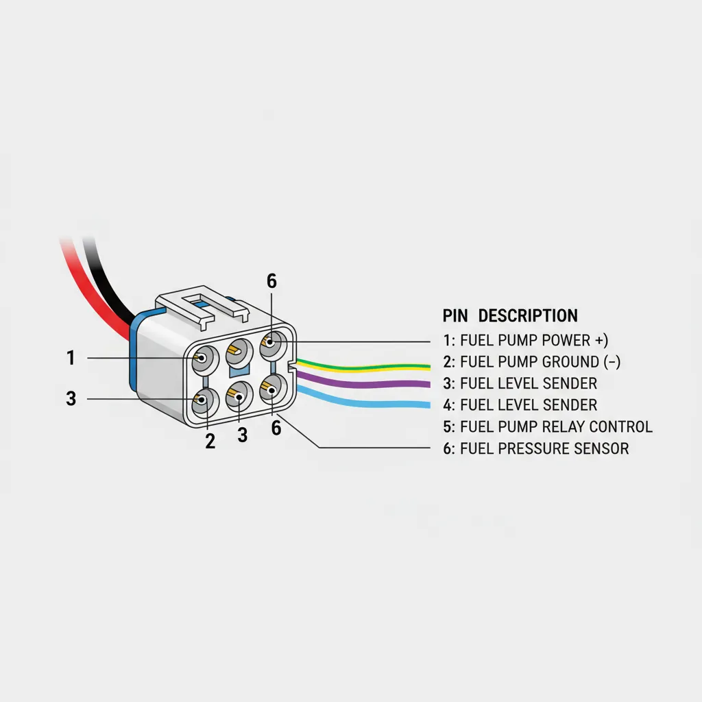
Detailed Pinout Functions: Power, Ground, and Sending Units
A typical Ram 1500 fuel pump connector serves two distinct systems: the high-current pump motor and the low-current fuel level sending unit. Understanding the separation of these circuits is critical for troubleshooting “gauge only” or “no-start only” issues.
- Fuel Pump Power: This pin receives 12V from the relay. During the initial “key on” phase, the PCM primes the system for roughly 2 seconds. In normal operation, the pump draws 5 to 10 amps. Any resistance here will cause the pump to run slow, leading to low fuel pressure.
- Main System Ground: This is the return path for the pump motor. Because of the high current draw, this wire is usually a larger gauge. A loose chassis ground can cause the pump to work intermittently or fail under load.
- Fuel Level Signal: The PCM sends a 5V reference signal to the fuel level sensor. The sensor is a variable resistor (potentiometer) moved by a float arm. The voltage that returns to the PCM tells the computer exactly how much fuel is in the tank.
- Sensor Ground (Clean Ground): To prevent the electrical “noise” of the pump motor from interfering with the fuel gauge, the sending unit uses an isolated ground. If this ground fails, you will often see a “fluttering” fuel gauge or a reading that stays at empty.
Never jump 12V directly to the sensor pins. The fuel level sending unit operates on a 5V reference; applying 12V can fry the resistor network on the pump assembly or damage the PCM input circuit.
Troubleshooting Connector Failure with a Digital Multimeter
Static voltage testing (checking for 12V with the pump unplugged) is often misleading. A circuit can show 12V on a meter but fail to provide enough amperage to run the pump if there is corrosion in the connector. Professional diagnostics require testing the circuit under load.
📋
Step-by-Step Diagnostic Guide
Using a back-probe technique at the connector, have an assistant turn the key to ‘ON’. You should see a 12V pulse. If no voltage is present, the issue lies upstream in the TIPM or relay.
With the pump running (or cranking), measure the voltage between the battery positive and the connector power pin. A drop of more than 0.5V indicates excessive resistance in the wiring or connector.
Measure ohms between the connector ground pin and a clean spot on the chassis. Resistance should be below 0.5 ohms. High resistance here is a common cause of pump overheating.
Research indicates that a voltage drop of just 1V at the fuel pump connector can result in a 10% decrease in fuel pressure. In a 5.7L Hemi, this can lead to lean-fire conditions, causing hesitation under acceleration or “random misfire” codes that are difficult to trace.
Professional Repair Strategies for Damaged Harnesses
If your inspection reveals “green crust” (corrosion) or charred plastic around the power and ground pins, the connector must be replaced. Simply cleaning the pins is a temporary fix that will likely leave you stranded again within weeks.
Correct Pigtail Splicing
When installing a new pigtail, do not use standard “crimpon” butt connectors without weatherproofing. The fuel pump harness is exposed to road salt and moisture. Always use adhesive-lined heat-shrink butt connectors or solder the connections and seal them with marine-grade shrink tubing. This prevents moisture from wicking into the copper wires and causing future resistance issues.
OEM vs. Aftermarket
I have encountered many aftermarket fuel pump assemblies where the connector pins are slightly thinner than the OEM Mopar standard. This leads to poor “pin tension,” where the female terminal doesn’t grip the male pin tightly. Always perform a “drag test” with a spare pin to ensure the connection is snug. If the pigtail wires feel significantly thinner than your factory harness, do not use it; it will overheat under the 10-amp load of the pump.
By The Numbers
Avg. Replacement Cost
Typical Lifespan (Miles)
Required Wire Gauge
Safety Protocols and Installation Best Practices
Working on the fuel system of a Dodge Ram 1500 is inherently dangerous due to the presence of gasoline vapors. Professional technicians follow strict safety protocols to mitigate the risk of fire or injury. According to expert tips, the most overlooked step is the proper depressurization of the lines.
- Depressurize the System: Locate the fuel pump fuse in the TIPM. Pull the fuse while the engine is idling and wait for it to stall. This bleeds off the 50-60 PSI of pressure in the lines, preventing a fuel spray when you disconnect the pump.
- Battery Disconnection: Always disconnect the negative battery terminal. A single spark from a dropped tool near the open fuel tank can be catastrophic.
- Use Proper Tools: Many mechanics use a screwdriver and hammer to rotate the locking ring. This can create sparks. Use a specialized fuel tank lock ring tool (like the Lisle 63600) for a safer and faster removal process.
- Final Verification: After replacing the connector or pump, cycle the key three times to prime the system. Check for leaks at the quick-connect fittings before fully securing the tank or bed.
✅ Proper Repair
- Sealed heat-shrink splices
- Dielectric grease on terminals
- OEM gauge pigtail wiring
- Secure harness routing
❌ Common Failures
- Twist-and-tape connections
- Broken safety locking tabs
- Corroded ground pins
- Thin aftermarket wiring
In summary, the Dodge Ram 1500 fuel pump connector is more than just a plug; it is the vital gateway for the energy that drives your truck. Understanding the specific wiring diagram for your model year—whether it’s a 3rd Gen with simple relay logic or a 5th Gen with PWM control—is the first step in a professional-grade diagnosis. Electrical integrity at the connector, including proper voltage and ground resistance, is just as critical as the pump motor itself. Always inspect for heat damage or corrosion and replace the pigtail connector if any signs of terminal spread or charring are present to ensure a long-lasting repair. For further technical data, consult your Mopar service manual or a trusted diagnostic database to ensure your specific VIN-based wiring matches the general diagrams provided here.
Frequently Asked Questions
Where is the fuel pump located on a Dodge Ram 1500?
The fuel pump is located inside the fuel tank, which is mounted on the driver’s side of the frame rail. Accessing the connector requires either lowering the fuel tank with a jack or removing the truck bed bolts to lift the bed and expose the top of the tank assembly for easier reach.
What are the wire colors for the fuel pump connector on my specific year Ram 1500?
Wire colors vary by generation. On many 4th Gen Rams (2009-2018), the fuel pump power wire is typically Dark Blue with a White stripe, and the ground is Solid Black or Black with an Orange stripe. However, always verify with a year-specific wiring diagram as Mopar often updates color codes mid-cycle.
How do I test the fuel pump connector with a multimeter?
Set your multimeter to DC Voltage. With the ignition in the ‘ON’ position (during the 2-second prime), check for 12V between the power pin and the ground pin. You should also perform a resistance test on the ground wire; it should show less than 0.5 ohms of resistance to the chassis ground.
What voltage should I see at the fuel pump connector?
During the initial priming stage or while the engine is cranking/running, you should see battery voltage (approximately 12.6V to 14.2V depending on alternator state). If you see significantly less voltage, such as 9V or 10V, there is high resistance in the wiring, a faulty relay, or a failing TIPM.
What are the symptoms of a bad fuel pump connector?
Common symptoms include intermittent stalling, a ‘no-start’ condition where the pump isn’t heard humming, or erratic fuel gauge readings. Visually, a bad connector often shows melted plastic around the pins, green corrosion inside the terminals, or a red locking tab that no longer secures the pigtail properly.


![2013 Ram 1500 Headlight Bulb Replacement: Complete Specs Guide [2026]](https://truckguider.com/wp-content/uploads/2026/03/2013-ram-1500-headlight-bulb-replacement-featured.webp)